
Inside-hole electroplated structure and manufacturing method thereof

A technology of in-hole electroplating and hole area, applied in circuits, electrical components, sputtering plating, etc., can solve the problems of time-consuming removal, lack of monitoring, photoresist residues, etc., to save costs and improve production efficiency.

Active Publication Date: 2020-02-11
福建省福联集成电路有限公司
View PDF4 Cites 0 Cited by
  • Summary
  • Abstract
  • Description
  • Claims
  • Application Information

AI Technical Summary

Problems solved by technology

The main problems are: sputtering and electroplating, so that the other metal layers to be removed are thicker, costly and time-consuming to remove; covering the etched holes with photoresist, the amount of photoresist is large and will cause abnormalities in the film surface. The photoresist will remain in the hole; lack of effective monitoring, it is impossible to determine the photoresist remaining in the hole except for the slivers

Method used


Image

  • Inside-hole electroplated structure and manufacturing method thereof
  • Inside-hole electroplated structure and manufacturing method thereof
  • Inside-hole electroplated structure and manufacturing method thereof

Examples


Embodiment Construction

[0043] In order to explain in detail the technical content, structural features, achieved goals and effects of the technical solution, the following will be described in detail in conjunction with specific embodiments and accompanying drawings.

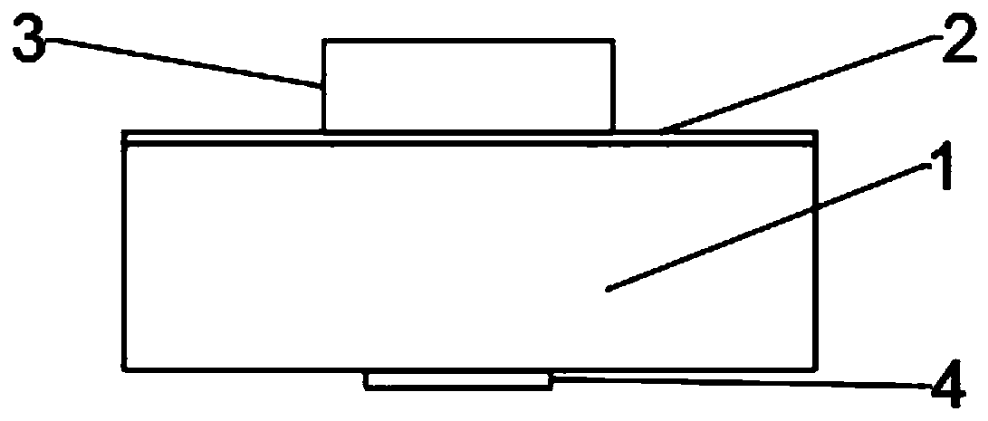
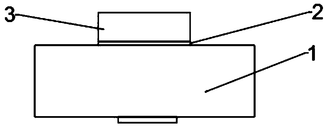
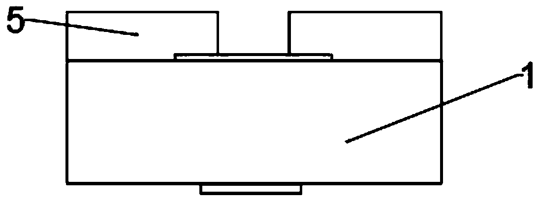
[0044] see Figure 1-Figure 10 , this embodiment provides a method for electroplating in holes. The holes of the present invention can be deep holes, and of course, in some embodiments, they can also be used on shallow holes. In some embodiments, the fabrication method can be fabricated on the backside of the semiconductor substrate 1 , and the fabrication process on the backside can be carried out after the fabrication of the front metal layer 4 is completed. The present embodiment at first will make hole, and making hole can adopt simple technology, specifically comprises the following steps: first after the first photoresist layer 5 is coated on semiconductor substrate 1, will etch at the perforated place (the hole place size and h...


PUM


Abstract

The invention discloses an inside-hole electroplated structure and a manufacturing method thereof. The method includes the following steps that a semiconductor substate is covered with a first photoresistor layer, and exposing and developing are conducted on the position of a to-be-manufactured hole; etching is conducted on the semiconductor substate with the first photoresistor layer as a mask, ahole is manufactured, the bottom of the hole is a metal layer on the other side of the semiconductor substrate, and the first photoresistor layer is removed; and seed crystal layer metal deposition is conducted. According to the scheme, after the hole with seed crystal layer metal is manufactured in the semiconductor substrate, dry film photoresist adheres to the semiconductor substrate, exposingand developing are conducted on a hole area, the metal is electroplated to the hole area, an electroplated metal layer is formed, the dry film photoresist is removed, the situation that due to the fact that after the inner portion of the hole is filled with photoresistors, the number of the photoresistors which are used is large, the film surface unusual condition is caused is avoided, and the situation that due to the fact that the photoresistors are left in the hole, the electroplating effect is influenced is also avoided; and meanwhile cost is saved, and the production efficiency is improved.

Description

technical field [0001] The invention relates to the technical field of semiconductor electroplating, in particular to an electroplating structure in a hole and a manufacturing method thereof. Background technique [0002] The traditional electroplating in the hole is through sputtering and electroplating on the whole surface, and then the hole area is covered with photoresist, and the other areas are removed by wet etching. The main problems are: sputtering and electroplating, so that the other metal layers to be removed are thicker, costly and time-consuming to remove; covering the etched holes with photoresist, the amount of photoresist is large and will cause abnormalities in the film surface. The photoresist will remain in the hole; without effective monitoring, it is impossible to determine that there is photoresist remaining in the hole except for the slivers. Contents of the invention [0003] For this reason, it is necessary to provide an electroplating method in ...

Claims


Application Information

Patent Timeline
IPC IPC(8): C25D5/02C25D7/12C23C14/34C23C14/18H01L21/768H01L23/48
CPCC23C14/185C23C14/34C25D5/022C25D7/12H01L21/76879H01L21/76898H01L23/481
Inventor 黄光伟李立中林伟铭吴淑芳马跃辉陈智广吴靖庄永淳
Owner 福建省福联集成电路有限公司
Learn More