An environmentally friendly and efficient sanitation vehicle

A sanitation vehicle, high-efficiency technology, applied in the field of sanitation vehicles, can solve the problems of increasing water supply and water supply pressure, loss of time and fuel consumption, and large water consumption of road sweepers, so as to reduce driving energy consumption, reduce pressure loss, reduce The effect of vehicle energy consumption

Pending Publication Date: 2018-12-11
邓东
View PDF0 Cites 3 Cited by
  • Summary
  • Abstract
  • Description
  • Claims
  • Application Information

AI Technical Summary

Problems solved by technology

This directly shortens the continuous and sustainable working time of the road sweeper, so in actual use, the road sweeper often needs to stop sweeping due to lack of water and go to the water source to add water, losing a lot of time and fuel consumption
[0019] 2) The work efficiency of the road sweeper is significantly reduced
The whole drainage process usually takes 10 minutes to 30 minutes, and the road sweeper usually drains water 2 to 6 times a day. Among them, the washing and sweeping car with a large water consumption usually needs to be drained every half an hour, which greatly reduces the cleaning time of the road sweeper. work efficiency
[0020] 3) The work efficiency of the road sweeper is significantly reduced
A very large garbage bin can actually only load very little garbage due to the above reasons, which leads to a reduction in the single continuous working capacity of the road sweeper
[0021] 4) The work efficiency of the road sweeper is significantly reduced
[0022] 5) Road sweepers consume a lot of water and waste water resources
At Nozzle 2 and Nozzle 3, the fine water mist used for spraying dust reduction and the passing garbage need to be fully contacted to achieve a good dust reduction effect, but the high-speed airflow here has a negative impact on the full contact between the two, and this shoul

Method used


Image

  • An environmentally friendly and efficient sanitation vehicle
  • An environmentally friendly and efficient sanitation vehicle
  • An environmentally friendly and efficient sanitation vehicle

Examples


Embodiment Construction

[0078] A kind of environment-friendly and high-efficiency sanitation vehicle of the present invention will be further described in detail below.

[0079] The invention will now be described in more detail with reference to the accompanying drawings, in which preferred embodiments of the invention are shown, it being understood that those skilled in the art may modify the invention described herein and still achieve the advantageous effects of the invention. Therefore, the following description should be understood as the broad knowledge of those skilled in the art, but not as a limitation of the present invention.

[0080] In the interest of clarity, not all features of an actual implementation are described. In the following description, well-known functions and constructions are not described in detail since they would obscure the invention with unnecessary detail. It should be appreciated that in the development of any actual embodiment, numerous implementation details mus...


PUM


Abstract

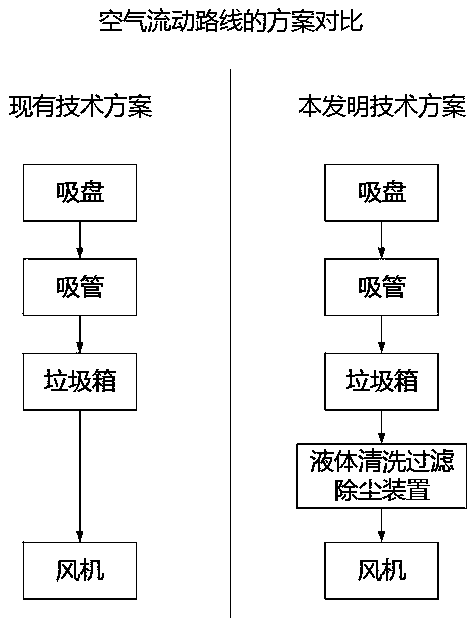
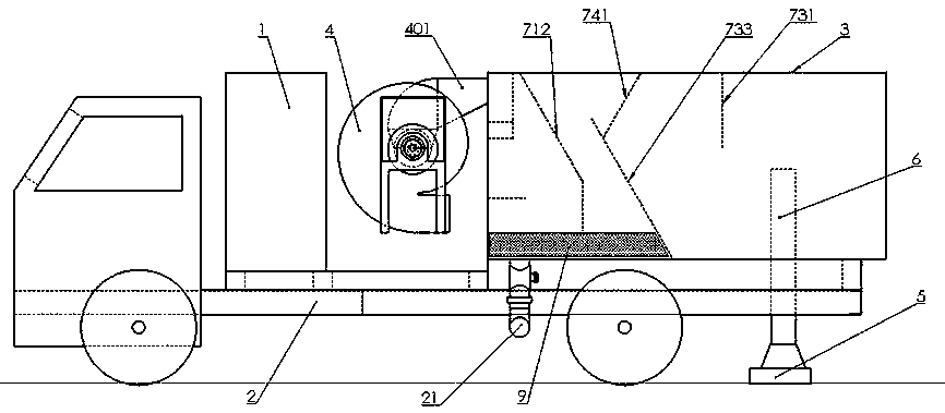
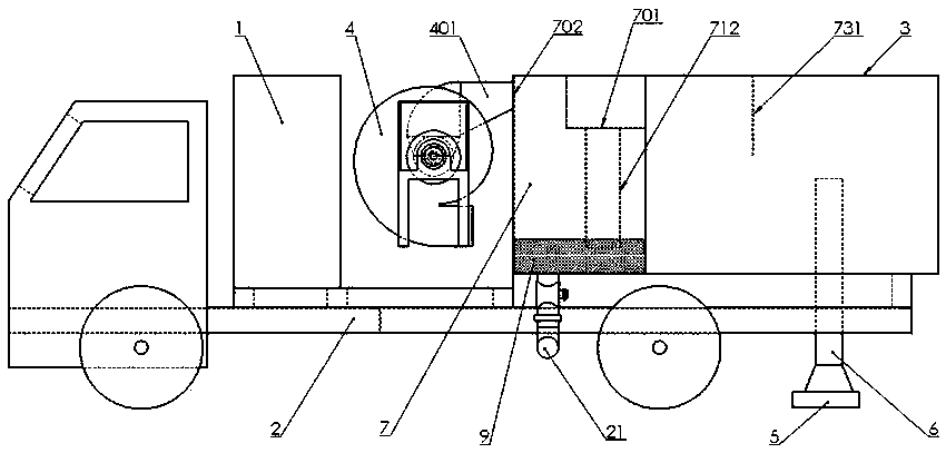
An environmentally-friendly and efficient sanitation vehicle comprises a vehicle chassis, a garbage bin, a fan, a suction nozzle, a suction pipe, a liquid cleaning and filtering dust removing device,wherein an inlet of the device is communicated with the garbage bin, an outlet of the device is communicated with the fan, and dust removing liquid is arranged in the chassis; the fan works to producenegative pressure, make garbage enter that suction pipe through the suction nozzle, and then enter the garbage bin, most garbage is deposited in the garbage bin, a small amount of dust enters and dissolves in the dust-removing liquid with the airflow, and the clean gas out of the dust-removing liquid is discharged through the fan. The invention can realize cleaner and environmentally friendly airdischarged from the blower of the sanitation vehicle and avoid secondary dust. Saving water; Significant reduction in vehicle energy consumption and exhaust emissions; Strong suction, long mileage, significantly improve the efficiency of the vehicle; Reduce the cost of manufacturing and using the vehicle, save time and labor for operators; Ensure that sanitation vehicles operate normally in winter; Reduce random dumping of sewage.

Description

technical field [0001] The invention relates to a special-purpose vehicle, including the field of municipal sanitation vehicles, and in particular to a sanitation vehicle with a liquid cleaning, filtering and dust-removing device, including road sweepers, sweepers, dust collectors, dry sweepers and the like. Background technique [0002] Road sweeper is a general term for a class of sanitation vehicles, including vehicle chassis, dustbins, centrifugal fans, suction cups (suction nozzles), suction pipes and accessories, of which the dustbin contains inlets, outlets and tailgates. Its basic working principle is that the suction nozzle is connected to the inlet of the suction pipe, the suction pipe is connected to the inlet of the dustbin, and the outlet of the dustbin is connected to the inlet of the centrifugal fan; the vehicle chassis carries these parts and drives at low speed on the road; Negative pressure is generated at the mouth, and the air and garbage on the road are ...

Claims


Application Information

Patent Timeline
IPC IPC(8): E01H1/08B01D50/00
CPCE01H1/0836B01D50/60
Inventor 邓东
Owner 邓东
Why Eureka
Try Eureka