Host structure of sliding-vane air compressor

An air compressor, sliding vane technology, used in machines/engines, rotary piston machinery, mechanical equipment, etc., can solve the problem of inability to seal, lubricate, reduce friction, dry friction between the rotor and the bearing seat, and reduce the efficiency of the entire unit and other problems, to achieve the effect of simple structure, small airflow loss, and increased sealing

Pending Publication Date: 2018-12-11
盐城中德劲博机电有限公司
View PDF5 Cites 4 Cited by
  • Summary
  • Abstract
  • Description
  • Claims
  • Application Information

AI Technical Summary

Problems solved by technology

The existing oil circuit design cannot expect to play a good role in sealing, lubricating and reducing wear
[0005] 3. In the existing sliding vane air compressor, the rotor rotates during the working process and generates relative motion with the fixed bearing seat. The end surface of the rotor middle and the inner end surface of the bearing seat will generate friction, which reduces the overall unit. When the lubrication is insufficient or the axial fit gap is too small to form an oil film, dry friction will occur between the rotor and the bearing seat, and in severe cases, the workpiece will be worn and scrapped

Method used


Image

  • Host structure of sliding-vane air compressor
  • Host structure of sliding-vane air compressor

Examples


Embodiment Construction

[0016] The specific content of the present invention will be described in detail below in conjunction with the accompanying drawings and specific embodiments.

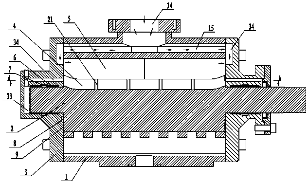
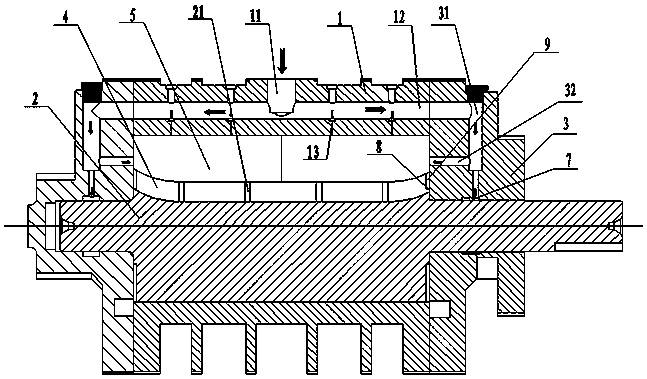
[0017] Such as figure 1 , figure 2 As shown, the main structure of the sliding vane air compressor includes a rotor 2 arranged in the cylinder block 1, the cylinder block 1 is used as a stator, and bearing housings 3 are respectively arranged on both sides of the cylinder block 1. The middle part of the rotor 2 is evenly provided with a number of slide grooves 4, and two sliding pieces 5 are slidably arranged in the slide grooves 4 that cooperate with each other. The two ends of the rotor 2 are respectively arranged on the bearing housing 3 through sliding bearings 6. Inside, the cylinder block 1 is provided with an oil inlet 11 and a main oil inlet passage 12, and a number of small oil inlet passages are uniformly arranged on the cylinder block 1 between the main oil inlet passage 12 and the sliding plate 5 13. Lub...


PUM


Abstract

The invention discloses an enhanced sealing structure for a sliding-vane air compressor with a simple structure and a good sealing effect. The enhanced sealing structure comprises a rotor arranged ina cylinder block, wherein the cylinder block is taken as a stator; bearing seats are arranged on both sides of the cylinder block; a plurality of sliding chutes are uniformly formed in the middle of the rotor; two sliding vanes are arranged in the sliding chutes matched with the sliding vanes in a sliding way; the two ends of the rotor are rotationally arranged in the bearing seats through slidingbearings respectively; an oil inlet and a main oil inlet passage are formed in the cylinder block; a plurality of oil inlet small passages are uniformly formed in the cylinder block between the mainoil inlet passage and the sliding vanes; lubricating oil is injected directly into the cylinder block through the plurality of oil inlet small passages, so that an oil film layer is formed between therotor and the sliding vanes as well as between the two sliding vanes; the two ends of the main oil inlet passage are provided with sliding bearing lubricating oil supply passages formed in the bearing seats respectively.

Description

technical field [0001] The invention relates to the technical field of air compressors, in particular to the main structure of a vane air compressor. Background technique [0002] The sliding vane air compressor is composed of a rotor and a stator, wherein the rotor is evenly opened with a number of longitudinal slide slots, and the slide vanes slide freely in the slide slots; the stator is a cylinder, and the rotor is placed eccentrically in the stator. When the rotor rotates, Under the action of centrifugal force, the sliding vanes are thrown out of the chute and are in close contact with the stator through the oil film. A closed air chamber is formed between two adjacent sliding vanes and the inner wall of the stator, which is the air compression chamber. When the rotor rotates, the air The volume of the compression chamber changes with the amount of sliding vane. During the suction process, the air is sucked into the compression chamber through the filter and mixed with ...

Claims


Application Information

Patent Timeline
Patent Type & Authority Applications(China)
IPC IPC(8): F04C18/344F04C29/00F04C29/02F04C29/04F04C27/00F16C35/02
CPCF04C18/344F04C27/008F04C29/00F04C29/0007F04C29/02F16C35/02F04C2240/50F04C2240/10F04C2240/20
Inventor 陈泽
Owner 盐城中德劲博机电有限公司
Why Eureka
Try Eureka