Locking device for extensile sockets

A locking device and socket technology, applied in the direction of fixing devices, mechanical equipment, etc., can solve the problems of high power consumption, short service life, high price, etc., and achieve easy production and use, ingenious and simple structure, and low cost Effect

Inactive Publication Date: 2018-12-11
东莞栢民电子有限公司
View PDF5 Cites 0 Cited by
  • Summary
  • Abstract
  • Description
  • Claims
  • Application Information

AI Technical Summary

Problems solved by technology

[0002] Lock buckle, the main function is to fasten two items. In the past, it generally refers to the buckle fastener installed on the door and window to lock the door and window. It is generally composed of a movable part and a fixed part. Through the connection between the movable part and the fixed part Combining and separating to achieve the closing and opening of doors and windows. With the continuous development of society and the continuous improvement of consumer demand, locks are widely used in many industries and play an important role in office, home and kitchen. At present, , there are many types of locking devices on the market, such as rotary, tensile and electric, etc., but there are also many shortcomings. Some locking devices are simple in structure, easy to install and low in price, but have a long service life. Insufficient in length, although some locking devices such as electric ones are convenient to use, they have shortcomings such as large power consumption, high price and complicated structure. At present, there is a lack of a simple structure, easy to use, low cost and easy to manufacture on the market. locking device

Method used


Image

  • Locking device for extensile sockets
  • Locking device for extensile sockets
  • Locking device for extensile sockets

Examples


Embodiment Construction

[0016] In order to make the object, technical solution and advantages of the present invention clearer, the present invention will be further described in detail below in conjunction with the accompanying drawings and embodiments. It should be understood that the specific embodiments described here are only used to explain the present invention, not to limit the present invention.

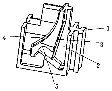
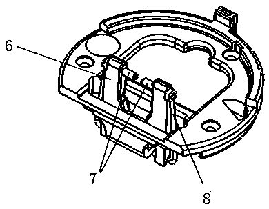
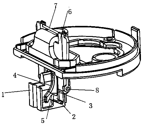
[0017] Such as Figure 1-Figure 3 As shown, a locking device for an elastic socket includes a sliding rod 7, a U-shaped circlip 8, a lock seat 1 and a fixed frame 6, and the lock seat 1 is provided with a guide groove 2 on the side, and the The guide groove 2 is provided with an ascending curved surface 3, a descending curved surface 4 and a stationary curved surface 5 on the inner side, and the fixed mount 6 includes a through hole and a groove, and the U-shaped retaining ring 8 is formed between the groove and the fixed mount 6. Tightly connected, one end of the sliding rod 7 passes through the ...


PUM


Abstract

The invention relates to the technical field of locking devices, in particular to a locking device for extensile sockets. The locking device comprises slide rods, a U-shaped circlip, a fastening seatand a fixing rack. The lateral side of the fastening seat is provided with a guide channel; the inner side of the guide channel is provided with an ascent surface, a descent surface and a static surface; the fixing rack includes through holes and a groove; the U-shaped circlip is tightly connected with the fixing rack via the groove; one end of each slide rod is passed through the corresponding through hole and connected with one end of the U-shaped circlip; the other end of every slide rod is slidably connected with the bottom of the guide channel. The locking device herein has the advantagesthat by using the mechanical principles and using the circlip as a power source, the slide rods of the locking device experience spatial curvilinear motion in the guide groove of the fastening seat,one travel for locking and one travel for moving are achieved, and the locking device is simple in structure, easy to produce and low in cost.

Description

technical field [0001] The invention relates to the technical field of locking devices, in particular to a locking device for an elastic socket. Background technique [0002] Lock buckle, the main function is to fasten two items. In the past, it generally refers to the buckle fastener installed on the door and window to lock the door and window. It is generally composed of a movable part and a fixed part. Through the connection between the movable part and the fixed part Combining and separating to achieve the closing and opening of doors and windows. With the continuous development of society and the continuous improvement of consumer demand, locks are widely used in many industries and play an important role in office, home and kitchen. At present, , there are many types of locking devices on the market, such as rotary, tensile and electric, etc., but there are also many shortcomings. Some locking devices are simple in structure, easy to install and low in price, but have ...

Claims


Application Information

Patent Timeline
Patent Type & Authority Applications(China)
IPC IPC(8): F16B1/02
CPCF16B1/02
Inventor 韩铮
Owner 东莞栢民电子有限公司
Why Eureka
Try Eureka