
Bevel gear and manufacturing method and mold thereof

A technology of bevel gears and molds, which is applied to belts/chains/gears, textiles and papermaking, and components with teeth, etc. It can solve the problems of bevel gears with high noise and fast wear, and achieve high yield, reduce energy consumption, The effect of improving stability

Pending Publication Date: 2018-12-11
浙江文源智能科技有限公司
View PDF12 Cites 0 Cited by
  • Summary
  • Abstract
  • Description
  • Claims
  • Application Information

AI Technical Summary

Problems solved by technology

[0003] The purpose of the present invention is to solve the defects that the existing four-twisting spindle steering mechanism needs to occupy the connection support space between the upper spindle bar and the lower spindle bar, and the bevel gear is noisy and wears quickly, and provides a four-twisting spindle that is suitable for high-speed operation. Bevel gears and manufacturing methods thereof

Method used


Image

  • Bevel gear and manufacturing method and mold thereof
  • Bevel gear and manufacturing method and mold thereof
  • Bevel gear and manufacturing method and mold thereof

Examples


Embodiment Construction

[0025] Specific embodiments of the present invention will be described in detail below in conjunction with the accompanying drawings.

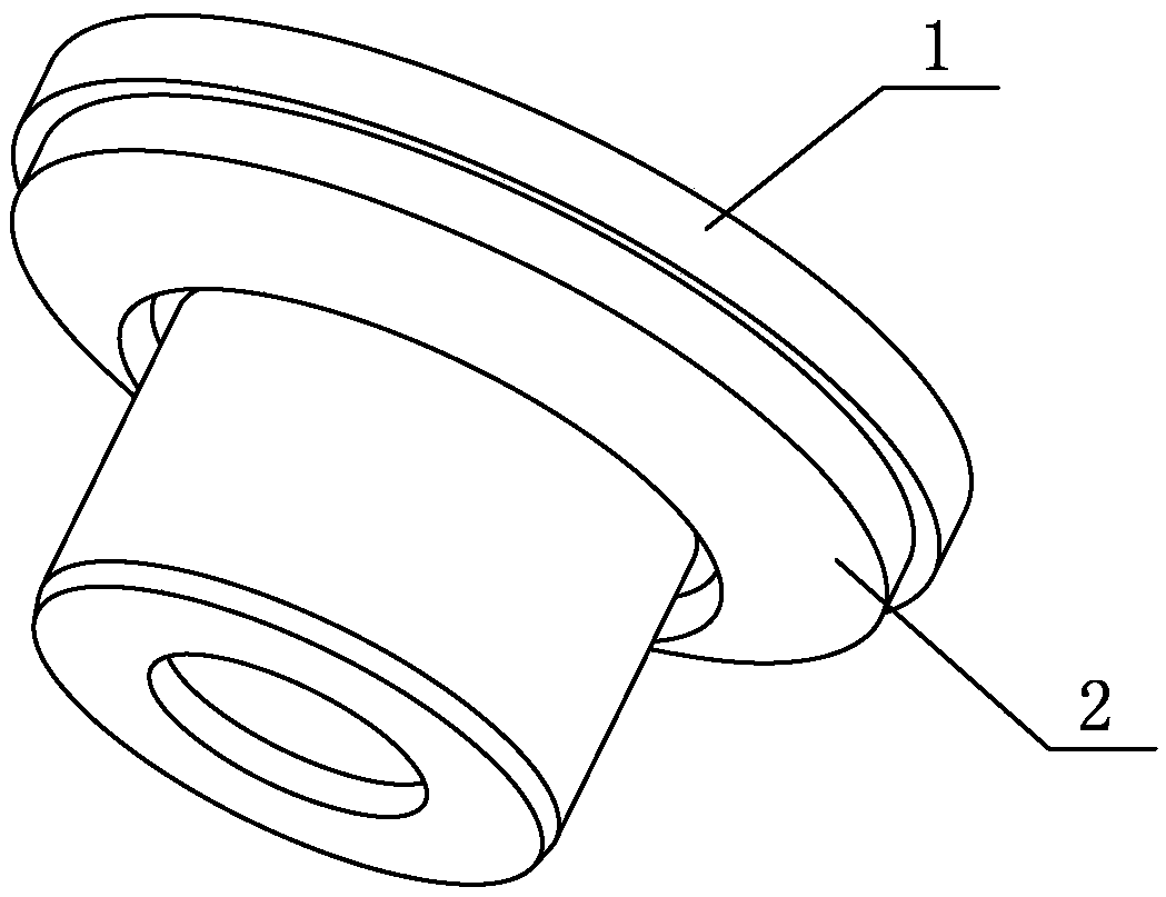
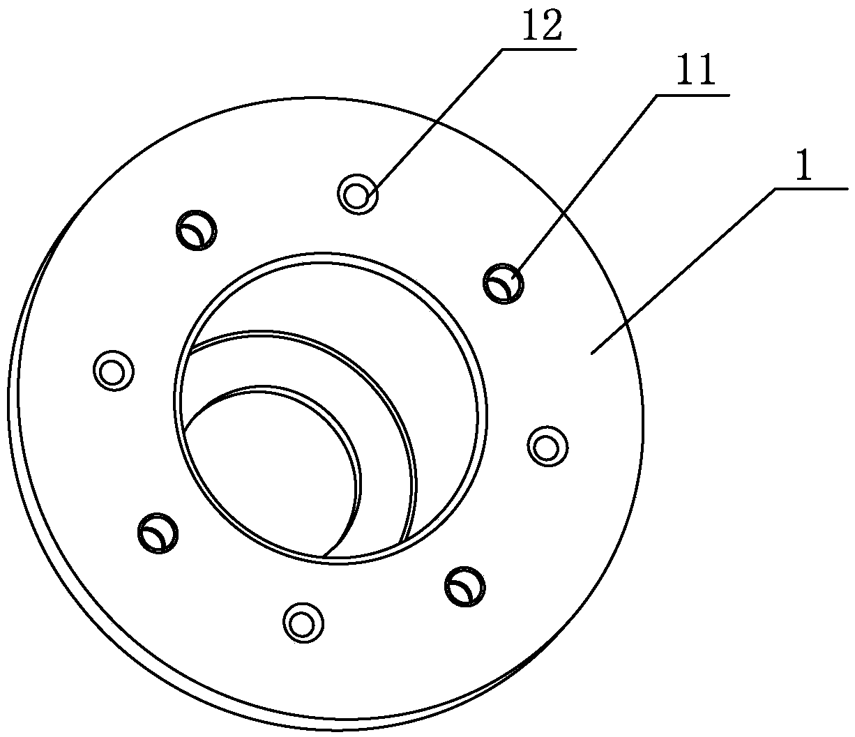
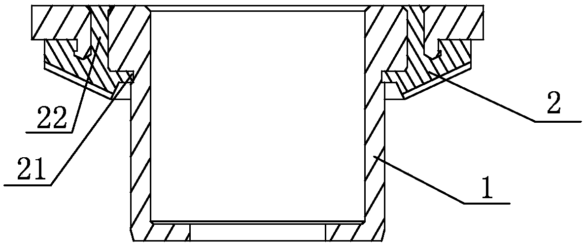
[0026] Such as Figure 1 ~ Figure 4 Shown is the first bevel gear embodiment of the present invention, Figure 5 ~ Figure 6 Shown is a second bevel gear embodiment of the present invention. The bevel gears of both embodiments include a metal skeleton 1 and a PEEK plastic ring gear 2 injection-molded on the skeleton. The skeleton includes a hub 14 and a web 13. The hub 14 and the web 13 are integrated, and the web is arranged along the circumferential direction. There are a plurality of limiting through holes 12, the top opening of the limiting through hole 12 is a trumpet-shaped opening with a large mouth facing upward, the ring gear 2 includes a wheel rim and gear teeth formed on the wheel rim, and the wheel rim is attached to the web 13 A convex post 22 extending into the limit through hole 12 is formed on the wheel rim. The top of the pro...


PUM


Abstract

The invention belongs to the field of spinning machinery and discloses a bevel gear and a manufacturing method and mold thereof. The bevel gear includes a metal framework and a PEEK plastic gear ringformed on the framework by means of injection molding. The framework includes a hub with an inner cavity and a web connected to the hub, multiple limiting through holes are circumferentially formed inthe web, the brim of the gear ring fits the web, and convex columns stretching into the limiting through holes are formed on the brim. During manufacturing, the framework is machined and formed at first, then the mold formed by combining a first half mold body with a second half mold body is used for containing the framework to serve as an insert for injection molding of the gear ring, the hub isinserted into a hub containing cavity of a mold chamber to achieve radial positioning, the top wall of the hub containing cavity presses against the second half mold body to achieve axial positioning, and a gear ring mold cavity is formed around the hub containing cavity, wherein the gear ring mold cavity and the hub containing cavity are both formed in the first half mold body. Injection outletscorresponding to the limiting through holes and an injection inlet are formed in the second half mold body, multipoint injection molding by means of the limiting holes is achieved, the filling effectis great, the qualification rate is high, and the wearing resistance and stability of the gear are excellent.

Description

technical field [0001] The invention belongs to the technical field of gears, and in particular relates to bevel gears, a manufacturing method and molds thereof. Background technique [0002] The existing four-twisted spindle steering mechanism adopts the upper bevel gear to transfer and support the upper and lower spindle rods, which needs to occupy the connecting support space between the upper and lower spindle rods, and participate in bearing the weight of the upper spindle, high-speed movement The upper spindle bar is prone to shaking, the steering mechanism is prone to vibration, and interacts with each other, and even easily generates resonance, resulting in a large vibration of the entire spindle, which cannot adapt to high-speed operation; the bevel gear is made of steel, and the gears are metal friction, which is noisy. Fast wear and short life. Contents of the invention [0003] The purpose of the present invention is to solve the defects that the existing four...

Claims


Application Information

Patent Timeline
Patent Type & Authority Applications(China)
IPC IPC(8): F16H55/17F16H55/06D01H1/242B29C45/14B29C45/26
CPCF16H55/06F16H55/17D01H1/242B29C45/14B29C45/26
Inventor 何燮锋
Owner 浙江文源智能科技有限公司
Learn More