
Suspender anchoring structure of embedded continuous beam-arch combined bridge

A beam-arch combination and anchoring structure technology, which is applied in bridges, bridge materials, bridge construction, etc., can solve problems such as limited size of concrete anchor blocks, unfavorable service life of suspenders, and influence on the durability of suspenders, so as to avoid the decline of construction quality , Avoid concrete cracking and reduce the risk of working at heights

Active Publication Date: 2021-12-03
CHINA RAILWAY ERYUAN ENG GRP CO LTD
View PDF7 Cites 0 Cited by
  • Summary
  • Abstract
  • Description
  • Claims
  • Application Information

AI Technical Summary

Problems solved by technology

The disadvantages of this structure are: firstly, the size of the concrete anchor block is limited, the local compressive stress of the anchor block is concentrated after the suspender is stretched, and the junction between the anchor block and the web is easy to crack; secondly, the anchor head at the lower end of the suspender is located on the flange of the main beam Under the slab, construction, installation, inspection and maintenance can only be done under the beam, which is extremely inconvenient to operate; thirdly, the anchor head at the bottom of the anchor block is completely exposed, which affects the durability of the boom and is not good for the service life of the boom

Method used


Image

  • Suspender anchoring structure of embedded continuous beam-arch combined bridge
  • Suspender anchoring structure of embedded continuous beam-arch combined bridge
  • Suspender anchoring structure of embedded continuous beam-arch combined bridge

Examples


Embodiment Construction

[0022] The present invention will be further described below in conjunction with the accompanying drawings and embodiments.

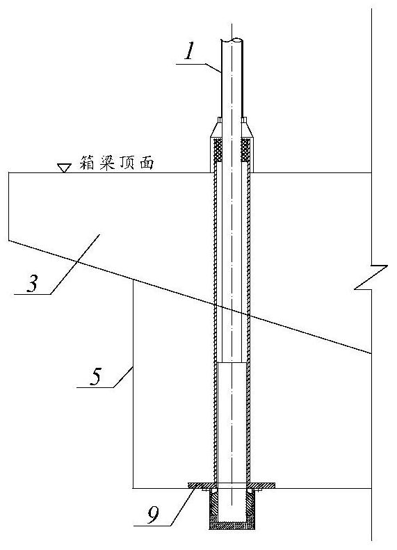
[0023] refer to figure 1 , the existing commonly used anchoring form is that the suspender 1 penetrates the box girder 3 and the beam 5, and the anchor plate 9 is pre-embedded at the bottom of the beam, and the suspender 1 is anchored below the beam 5.

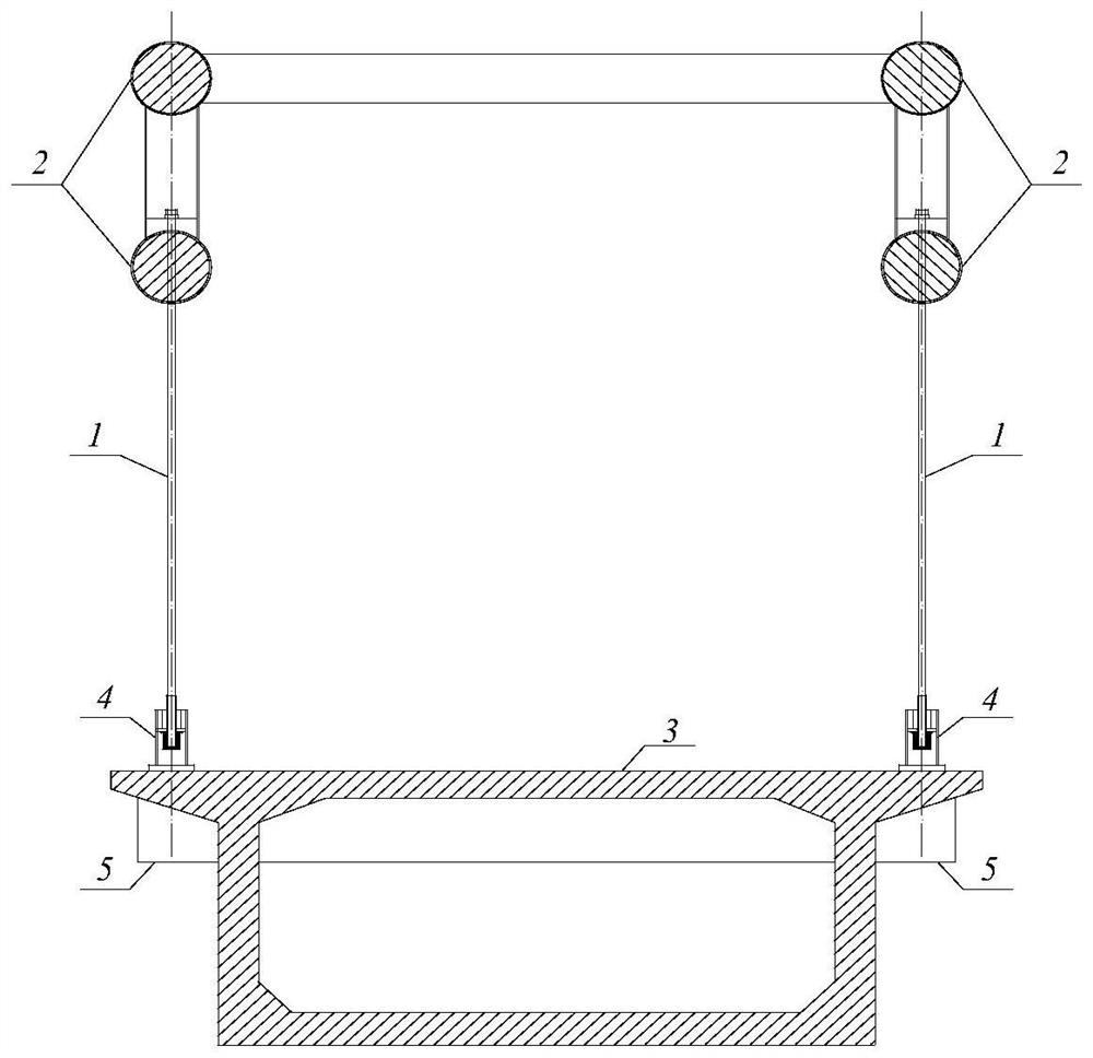
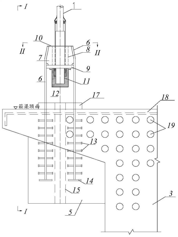
[0024] refer to figure 2 , a kind of suspender anchorage structure of the embedded continuous beam-arch composite bridge of the present invention, the arch rib 2 and the concrete box girder 3 are connected through the suspender 1 to form a whole, and the box girder 3 is provided with a beam 5 to strengthen the transverse rigidity of the beam body. The upper end of the boom 1 is a fixed end, which is fixedly connected with the arch rib 2 of the boom 1 through the anchor head, and the anchor head is located in the abdominal cavity of the arch rib 2 or between the upper and lower chords. The lower end o...


PUM


Abstract

A suspender anchoring structure of an embedded continuous beam-arch combined bridge effectively simplifies suspender tensioning and anchoring construction processes, avoids local pressure-bearing stress concentration of an anchor head, reduces design and construction difficulty, and greatly improves maintenance and repair conditions of a bridge suspender during operation. The upper end of the suspender is a fixed end and is fixedly connected with the suspender arch rib through the anchor head, and the lower end of the suspender is a tensioning end and is in anchoring connection with the box girder and the cross beam through the suspender anchoring component. The suspender anchoring component comprises a pair of anchor pulling plates which are arranged at intervals in the bridge direction, the lower portions of the pair of anchor pulling plates are embedded in concrete of a box girder and a cross beam, anti-shear components are welded to the plate faces, the concrete tightly wraps the anti-shear components to form anti-shear connecting pieces, and the anti-shear connecting pieces and the anchor pulling plates jointly form the tensile anchoring device. The upper portions of the pair of anchoring plates are exposed on a bridge floor and used for installing, fixing and tensioning anchorage devices at the tensioning ends of the suspenders, the anchoring bearing plate is located between the pair of anchoring plates and welded to the plate faces of the anchoring plates, the two suspenders are anchored on the anchoring bearing plate at the same time, and a double-suspender system is formed.

Description

technical field [0001] The invention relates to the technical field of bridge engineering, in particular to a suspender anchorage structure of an embedded continuous beam-arch composite bridge. Background technique [0002] In recent years, my country's railway construction has achieved rapid development, and a large number of long-span complex bridges with novel structures, complex technologies and difficult construction have been built. Among them, the continuous beam (rigid frame) arch composite system bridge is a typical representative. This bridge type is a reasonable choice when the conventional three-span continuous structure span cannot meet the design requirements, and a larger-span bridge structure needs to be used to cross roads or navigable rivers, and the clear height under the bridge is limited by the line elevation. The continuous beam (rigid frame) arch composite system bridge has the characteristics of large spanning capacity, small construction interferenc...

Claims


Application Information

Patent Timeline
Patent Type & Authority Applications(China)
IPC IPC(8): E01D12/00E01D19/00E01D19/14E01D21/00E01D101/24
CPCE01D12/00E01D19/00E01D19/14E01D21/00E01D2101/24
Inventor 黄毅陈克坚刘伟徐勇易大伟胡玉珠游励晖王应良
Owner CHINA RAILWAY ERYUAN ENG GRP CO LTD
Learn More