
Gas leakage monitoring system on basis of distributed optical fiber sensing technologies

A distributed optical fiber and gas leakage technology, which is applied in the pipeline system, fluid tightness test, machine/structural component test, etc., can solve the problems of low efficiency, poor real-time performance, fire pollution environment, etc., and achieve high efficiency and monitoring The effect of long distance and large long-term benefits

Pending Publication Date: 2018-12-11
PINGHU BOHUI COMM TECH +1
View PDF7 Cites 0 Cited by
  • Summary
  • Abstract
  • Description
  • Claims
  • Application Information

AI Technical Summary

Problems solved by technology

[0002] Gas pipeline leakage will not only cause huge economic losses to the gas company, induce fires and pollute the environment, but also affect the use of gas users, and even endanger the personal safety of residents around the pipeline
The existing pipeline leakage detection methods include: segmental pressure method, magnetic flaw detection method, negative pressure method, etc., which require a lot of manpower and time to detect, poor real-time performance, and relatively low efficiency
[0003] Long-distance monitoring of pipelines requires a lot of manpower and material resources, and there is still the possibility of accidents due to work mistakes that lead to insufficient monitoring

Method used


Image

  • Gas leakage monitoring system on basis of distributed optical fiber sensing technologies
  • Gas leakage monitoring system on basis of distributed optical fiber sensing technologies
  • Gas leakage monitoring system on basis of distributed optical fiber sensing technologies

Examples


Embodiment Construction

[0033] The following will clearly and completely describe the technical solutions in the embodiments of the present invention with reference to the accompanying drawings in the embodiments of the present invention. Obviously, the described embodiments are only some, not all, embodiments of the present invention. Based on the embodiments of the present invention, all other embodiments obtained by persons of ordinary skill in the art without making creative efforts belong to the protection scope of the present invention.

[0034] In describing the present invention, it should be understood that the terms "longitudinal", "transverse", "upper", "lower", "front", "rear", "left", "right", "vertical", The orientation or positional relationship indicated by "horizontal", "top", "bottom", "inner", "outer", etc. are based on the orientation or positional relationship shown in the drawings, and are only for the convenience of describing the present invention and simplifying the descriptio...


PUM


Abstract

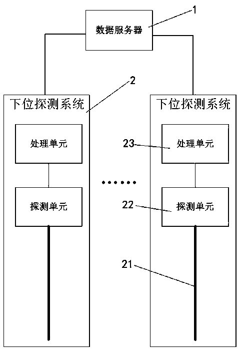
The invention discloses a gas leakage monitoring system on the basis of distributed optical fiber sensing technologies. The gas leakage monitoring system comprises a data server and a plurality of lower detection systems. The lower detection systems comprise sensing optical fibers, detection units and processing units, the sensing optical fibers are fixed onto gas pipelines, the detection units are connected with the sensing optical fibers, and the processing units are communicated and connected with the detection units and are communicated and connected with the data server; the detection units comprise transmission modules, receiving modules, timing modules, phase difference acquisition modules and photoelectric signal conversion modules, the transmission modules are used for transmitting light pulses to the sensing optical fibers, back scattering in the sensing optical fibers can be received by the receiving modules, the timing modules are connected with the transmission modules andthe receiving modules, the phase difference acquisition modules are connected with the transmission modules and the receiving modules, the photoelectric signal conversion modules are connected with the phase difference acquisition modules, and the photoelectric signal conversion modules and the timing modules are communicated and connected with the processing units. The gas leakage monitoring system has the advantages that integral vibration states of pipelines can be monitored by the gas leakage monitoring system, leakage conditions of the pipelines can be analyzed by the gas leakage monitoring system, and an alarm can be given by the gas leakage monitoring system.

Description

technical field [0001] The invention belongs to the field of pipeline leakage monitoring, in particular to a gas leakage monitoring system based on distributed optical fiber sensing technology. Background technique [0002] Gas pipeline leakage will not only cause huge economic losses to the gas company, induce fires and pollute the environment, but also affect the use of gas users, and even endanger the personal safety of residents around the pipeline. Existing pipeline leakage detection methods include: segmental pressure method, magnetic flaw detection method, negative pressure method, etc., which require a lot of manpower and time to detect, poor real-time performance, and relatively low efficiency. [0003] Long-distance monitoring of pipelines consumes a lot of manpower and material costs, and there is still the possibility of accidents caused by incomplete monitoring due to work mistakes. Contents of the invention [0004] Aiming at the problems existing in the pri...

Claims


Application Information

Patent Timeline
Patent Type & Authority Applications(China)
IPC IPC(8): F17D5/06F17D5/00G01M3/24
CPCF17D5/005F17D5/06G01M3/243
Inventor 王源江菅云峰张静黎载红
Owner PINGHU BOHUI COMM TECH
Learn More