
High-speed railway viaduct hydroelectric generation and rainwater collection irrigation system based on potential energy

A technology for irrigation systems and iron bridges, applied in the field of irrigation systems, can solve the problems of increased drainage difficulty in drainage systems under bridges, reduced service life of pier bases, and waste of hydraulic resources, etc., to achieve easy installation and implementation, prolong life, and save energy. energy effect

Pending Publication Date: 2020-02-21
BEIJING INSTITUTE OF TECHNOLOGYGY
View PDF0 Cites 0 Cited by
  • Summary
  • Abstract
  • Description
  • Claims
  • Application Information

AI Technical Summary

Problems solved by technology

[0003] my country's high-speed rail technology is at the advanced level in the world, and the total mileage of the high-speed rail is considerable. On the viaduct running on the high-speed rail, there is a complete drainage and rain drainage system to drain the rainwater to the bridge. When the rainfall is small, this rain drainage system can well maintain the high-speed rail viaduct. At the same time, the running environment of high-speed EMU trains will not have adverse effects on the ground under the bridge; but when the rainfall is large, the rainwater directly converging in the drainage pipeline will continuously impact the ground and the bottom of the pier, and will affect the drainage system under the bridge. The diversion and drainage capacity of the bridge has higher requirements, which will reduce the service life of the base of the bridge pier and make drainage of the drainage system under the bridge more difficult. Process Hydro Resources

Method used


Image

  • High-speed railway viaduct hydroelectric generation and rainwater collection irrigation system based on potential energy
  • High-speed railway viaduct hydroelectric generation and rainwater collection irrigation system based on potential energy
  • High-speed railway viaduct hydroelectric generation and rainwater collection irrigation system based on potential energy

Examples


Embodiment Construction

[0039] The specific embodiments of the present invention will be further described below in conjunction with the accompanying drawings. It should be clear here that the specific implementations given are only for explaining and helping understanding of the present invention, and are not intended to limit the present invention.

[0040]In the description of the present invention, it should be noted that the orientations or positional relationships indicated by the terms "vertical", "upper", "lower", "parallel", "left and right" are based on the orientations or positions shown in the drawings The relationship is only for the convenience of describing the present invention and simplifying the description, but does not indicate or imply that the referred device or element must have a specific orientation, be constructed and operated in a specific orientation, and thus should not be construed as a limitation of the present invention.

[0041] In the description of the present inven...


PUM


Abstract

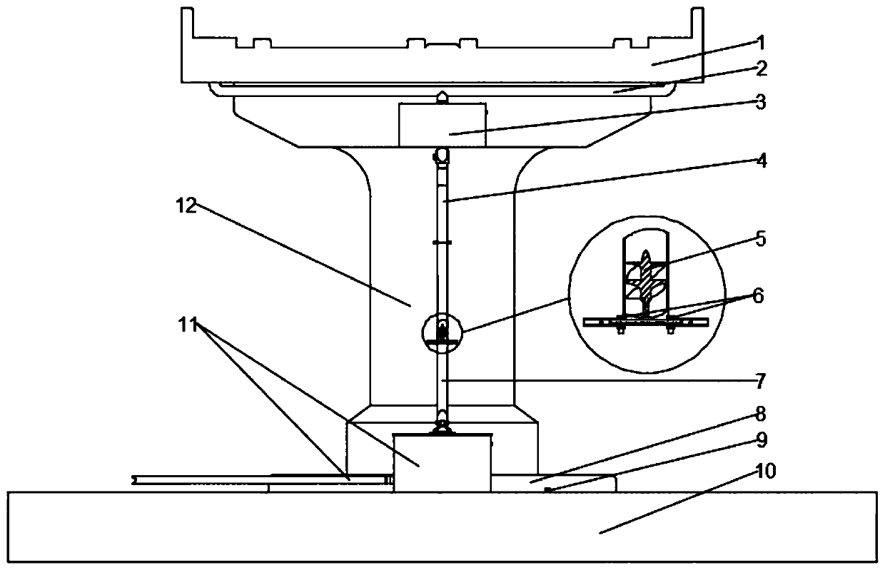
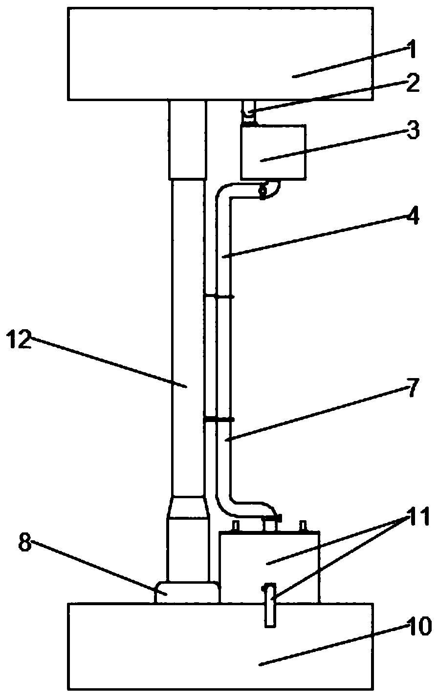
The invention discloses a high-speed railway viaduct hydroelectric generation and rainwater collection irrigation system based on potential energy, and belongs to the technical field of energy recycling and rainwater recycling. The system comprises a hydroelectric generation subsystem and a water storage irrigation subsystem; in the rainy days, an impeller outer rotor generator is driven by potential energy of falling rainwater to generate electricity, and then the rainwater is drained and stored in a low-position water collecting tank; and in sunny days, after a low-position water collectingtank control module sends a control instruction, a water outlet valve of the low-position water collecting tank is opened, and the rainwater stored in the low-position water collecting tank can automatically flow downwards by means of the potential energy produced by altitude difference between the low-position water collecting tank and to-be-irrigated ground so as to irrigate farmlands and greenbelts. By means of the potential energy of the falling rainwater, energy is recycled; by means of the low-position water collecting tank, impact of the rainwater on the ground is reduced, and the service life of the ground and foundations is prolonged, and meanwhile, the rainwater is collected for irrigation, so that rainwater resource is sufficiently utilized.

Description

technical field [0001] The invention belongs to the technical fields of energy recovery and utilization and rainwater recovery and reuse, and specifically belongs to a system for generating electricity by utilizing the potential energy of rainwater falling on a high-speed railway bridge, and collecting rainwater for irrigation at the same time. Background technique [0002] With the development of economy and social progress, the human demand for water resources is increasing day by day, coupled with the widespread irrational use of water resources, many countries and regions have faced the problem of water resource shortage. In order to alleviate this problem, an effective solution is to develop and utilize water resources in seawater, polar glaciers and other places; another method is to recycle and reuse water resources, in which rainwater resources are widely distributed as recyclable water resources , is an important research object in the field of water resource recycl...

Claims


Application Information

Patent Timeline
Patent Type & Authority Applications(China)
IPC IPC(8): F03B13/00A01G25/02
CPCF03B13/00F03B3/04F03B15/00E03B3/02E01D19/086A01G25/02A01G25/16H02K7/1823Y02E10/20
Inventor 黄小羽王义春李亚文
Owner BEIJING INSTITUTE OF TECHNOLOGYGY
Learn More