
Differential positioning system and method based on vehicle-road coordination system

A technology of differential positioning and vehicle-road coordination, applied in satellite radio beacon positioning system, service based on location information, service based on specific environment, etc., can solve the problems of limited distance, traffic cost, increased hardware cost, etc., and achieve the goal of using Convenient and flexible, traffic cost saving, and cost saving effects

Inactive Publication Date: 2018-12-11
北京星云互联科技有限公司
View PDF5 Cites 21 Cited by
  • Summary
  • Abstract
  • Description
  • Claims
  • Application Information

AI Technical Summary

Problems solved by technology

[0005] In the implementation of the above-mentioned differential positioning, the difference correction information is generally transmitted between the differential base station and the positioning terminal through the mobile operator network or the wireless data transmission station. On the one hand, since the differential base station and each positioning terminal need to configure additional communication Equipment, which will undoubtedly increase a lot of hardware costs; on the other hand, using the mobile operator network will also generate certain traffic charges, and when the network signal is not good, the effect of differential positioning will be affected
If you use a wireless data transmission station, although you do not need to pay traffic fees, the disadvantage is that the distance is limited and the coverage is small. Therefore, the current differential positioning method is obviously not suitable for the application of intelligent networked vehicles.

Method used


Image

  • Differential positioning system and method based on vehicle-road coordination system
  • Differential positioning system and method based on vehicle-road coordination system
  • Differential positioning system and method based on vehicle-road coordination system

Examples


Embodiment Construction

[0059] The preferred embodiments of the present invention will be described below with reference to the accompanying drawings. It should be understood that the preferred embodiments described here are only used to illustrate and explain the present invention, and are not used to limit the present invention.

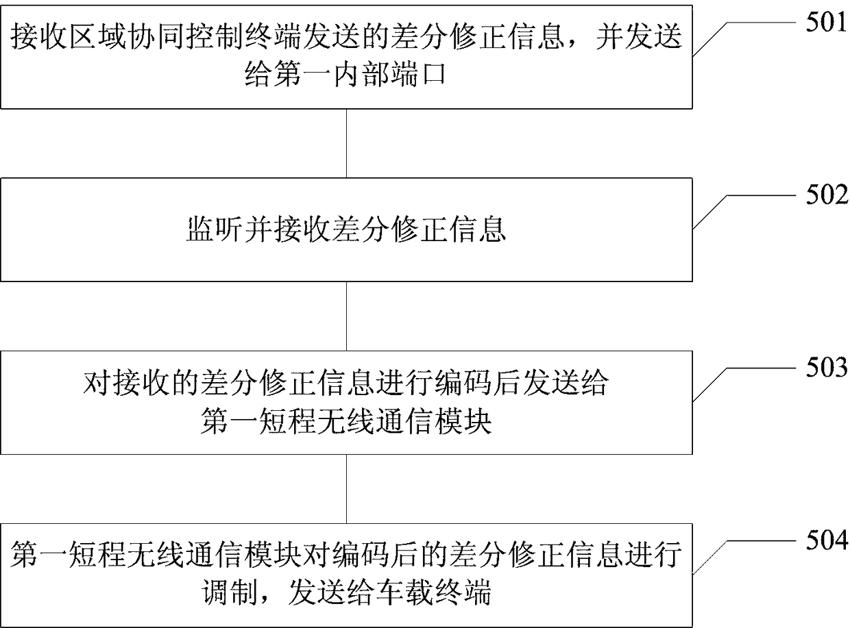
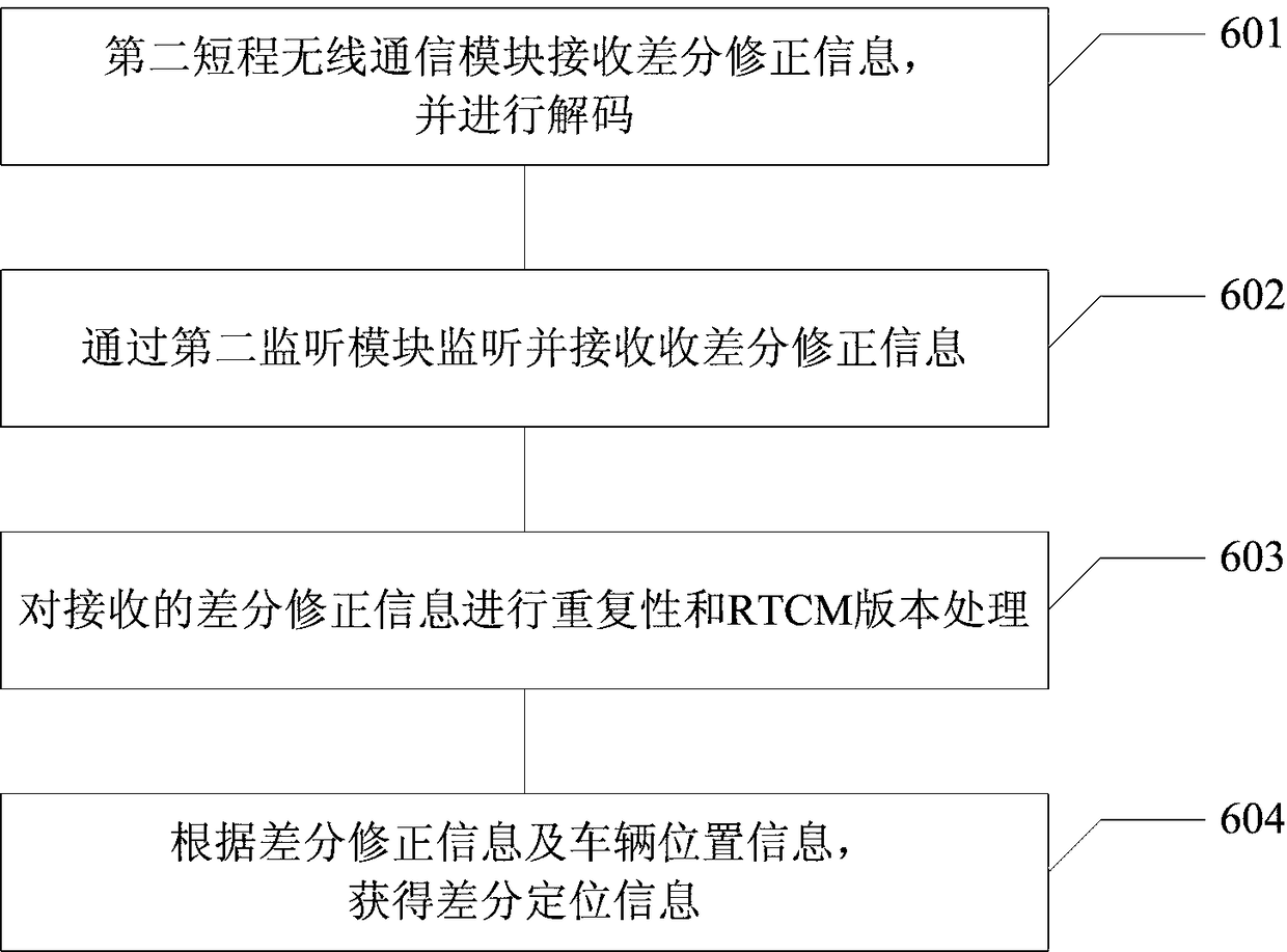
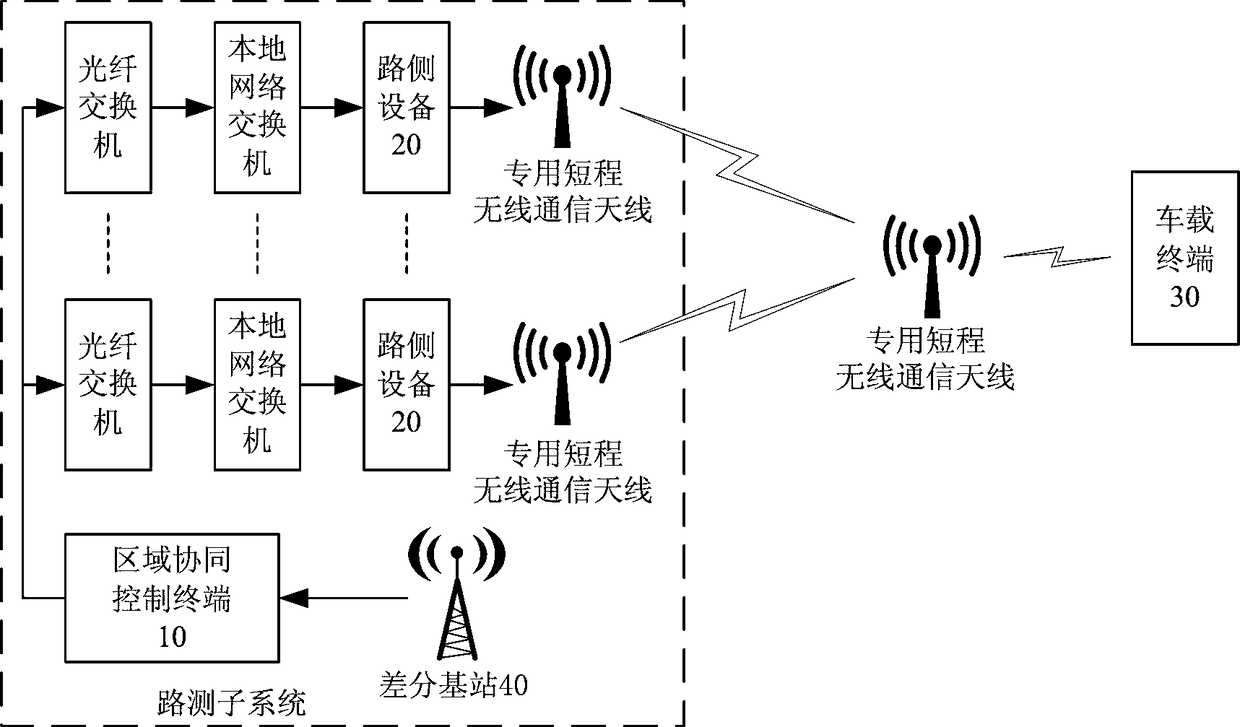
[0060] figure 1 It is a structural diagram of the differential positioning system based on the vehicle-road cooperative system according to the present invention, such as figure 1 As shown, the differential positioning system based on the vehicle-road collaborative system of the present invention includes two parts: a roadside subsystem and a vehicle-mounted terminal 30. The roadside subsystem is responsible for the network interaction of local intersections and the realization of collaborative application scenarios, and is responsible for the area Coordinated edge computing; the vehicle-mounted terminal 30 obtains original positioning information through the GPS positioning m...


PUM


Abstract

A differential positioning system based on a vehicle-road coordination system comprises a road test subsystem and an onboard terminal. The road test subsystem generates differential correction information and transmits the same to the onboard terminal. The onboard terminal generates differential positioning information of a vehicle by using acquired vehicle original positioning information and thedifferential correction information. The road test subsystem further comprises a differential base station, a regional coordinated control terminal, a roadside terminal. The differential base stationgenerates the differential correction information according to the accurate coordinates of its own position and the acquired changed positioning information. The regional coordinated control terminaltransmits the differential correction information to a plurality of roadside devices in the region of the regional coordinated control terminal. The roadside devices broadcast the differential correction information to the onboard terminal within its coverage. The invention also provides a differential positioning method based on a vehicle-road coordination system to provide high-precision positioning information for intelligent network-connected vehicles and unmanned vehicles.

Description

Technical field [0001] The present invention relates to the technical field of intelligent vehicle-road coordination, in particular to a differential positioning system and method based on a vehicle-road coordination system. Background technique [0002] Intelligent networked cars are equipped with advanced on-board sensors, controllers, actuators and other devices, and integrate modern communication and network technologies to realize intelligent information exchange and sharing between cars and X (cars, roads, people, clouds, etc.), and have a complex environment Perception, intelligent decision-making, collaborative control and other functions. It can realize safe, efficient, comfortable and energy-saving driving, and finally realize a new generation of cars that can replace humans. [0003] As a basic support technology for intelligent networked vehicles, high-precision positioning is an important source of environmental information for vehicles. Currently, the commonly used ...

Claims


Application Information

Patent Timeline
IPC IPC(8): G01S19/41H04L29/06H04L29/08H04W4/02H04W4/44
CPCG01S19/41H04L67/12H04L69/18H04L69/22H04W4/025H04W4/44
Inventor 王文学石勇王易之
Owner 北京星云互联科技有限公司
Learn More