a light intensity modulator

A light intensity modulation and grating coupling technology, applied in instruments, optics, nonlinear optics, etc., can solve the problems of difficult to achieve effective light intensity modulation, low modulation efficiency, etc., to reduce tolerance, improve modulation efficiency, and electro-absorption. Efficiency improvement effect

A light intensity modulation and grating coupling technology, applied in instruments, optics, nonlinear optics, etc., can solve the problems of difficult to achieve effective light intensity modulation, low modulation efficiency, etc., to reduce tolerance, improve modulation efficiency, and electro-absorption. Efficiency improvement effect

CN108983446BActive Publication Date: 2021-04-06TCL CORPORATION

Image

  • a light intensity modulator
  • a light intensity modulator

Examples


Embodiment Construction

[0013] In order to make the object, technical solution and advantages of the present invention more clear, the present invention will be further described in detail below in conjunction with the examples. It should be understood that the specific embodiments described here are only used to explain the present invention, not to limit the present invention.

[0014] In the description of the present invention, it should be understood that the terms "first" and "second" are used for description purposes only, and cannot be interpreted as indicating or implying relative importance or implicitly indicating the quantity of indicated technical features. Thus, a feature defined as "first" and "second" may explicitly or implicitly include one or more of these features. In the description of the present invention, "plurality" means two or more, unless otherwise specifically defined.

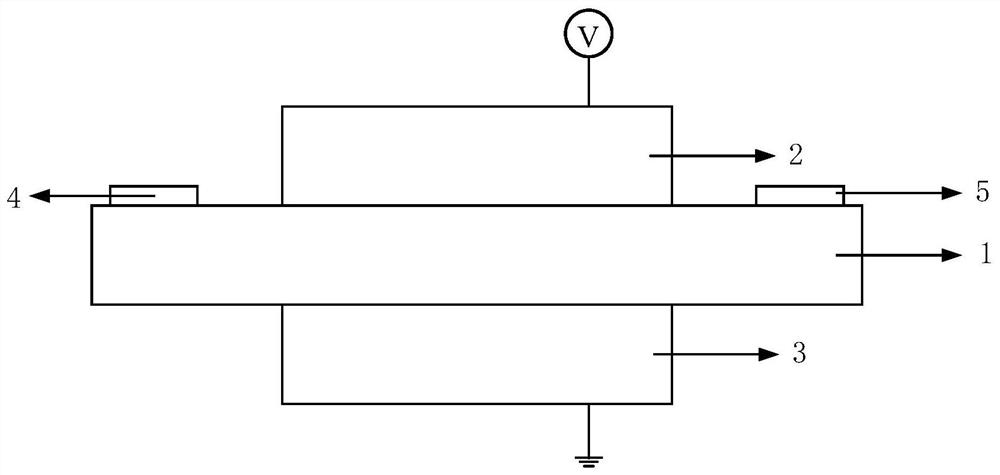
[0015] see figure 1 , an embodiment of the present invention provides an optical intensity modulator,...


PUM

PropertyMeasurementUnit
thicknessaaaaaaaaaa
thicknessaaaaaaaaaa

Abstract

The invention belongs to the technical field of display applications and provides a light intensity modulator. The optical intensity modulator provided by the present invention includes a first electrode, a planar optical waveguide, a second electrode, an incoupling module, and an outcoupling module. The planar optical waveguide includes at least one quantum dot layer and at least one dielectric layer that are laminated and combined. The electroabsorption efficiency of the quantum dot material in the dot layer is more than an order of magnitude higher than that of the bulk material of the same material, which greatly improves the electroabsorption efficiency of the light intensity modulator; at the same time, the stacking of the quantum dot layer and the dielectric layer The structure can effectively improve the control of the refractive index distribution in the waveguide, thereby reducing the tolerance of the waveguide to the light-guided mode and improving the modulation efficiency of light intensity.

Description

technical field [0001] The invention belongs to the technical field of display applications, in particular to a light intensity modulator. Background technique [0002] An optical modulator is a device that adjusts light wave parameters (such as light intensity, polarization, phase, etc.) by using an external signal. It is a key device for high-speed, short-distance optical communication and an important integrated optical device. Wherein, the light intensity modulator is used to adjust the light intensity by using an external signal. [0003] The working principle of the existing waveguide optical intensity modulator controlled by an external electric field is as follows: when no external electric field is applied, the light guide is in a normal guided mode state, and the outcoupling section will receive a constant output; When an external electric field parallel to the section of the waveguide is applied, the optical constant of the material in the waveguide will change d...

Claims


Application Information

Patent Timeline
06 Apr 2021
Publication
CN108983446B
IPC
G02F1/13
CPC
G02F1/13
Inventors
陈崧; 曹蔚然