
Method and device for determining shadow effect and electronic device

A determination method and shadow technology, applied in the field of image processing, can solve the problems of poor framing effect, physical exhaustion, high cost, etc., and achieve the effect of improving acquisition quality, realistic shadow effect, and beautiful appearance.

Inactive Publication Date: 2018-12-11
PACIFIC FUTURE TECH (SHENZHEN) CO LTD
View PDF12 Cites 2 Cited by
  • Summary
  • Abstract
  • Description
  • Claims
  • Application Information

AI Technical Summary

Problems solved by technology

In order to avoid poor framing effect caused by shaking of the handheld device, resulting in subsequent image processing problems, or users holding the mobile phone for a long time to watch videos and resulting in physical exhaustion, it is often necessary to install the mobile phone on a fixed bracket to keep it stable. The special camera bracket is of course effective. Quite good, but the cost is expensive and the volume is large. Ordinary users often use a simple mobile phone stand to achieve the required viewfinder effect and stable support. However, the usual simple stand is located on the protective case of the mobile phone or pasted on the On the back of the mobile phone, more and more users are unwilling to use mobile phone protective cases and simple sticky brackets because of the increasingly strong glass of mobile phones, the problem of heat dissipation of mobile phones, and the aesthetics of mobile phones.

Method used


Image

  • Method and device for determining shadow effect and electronic device
  • Method and device for determining shadow effect and electronic device
  • Method and device for determining shadow effect and electronic device

Examples


Embodiment Construction

[0037] In order to enable those skilled in the art to better understand the technical solutions in the embodiments of the present invention, the following will clearly and completely describe the technical solutions in the embodiments of the present invention in conjunction with the accompanying drawings in the embodiments of the present invention. Obviously, the described The embodiments are only some of the embodiments of the present invention, but not all of them. All other embodiments obtained by persons of ordinary skill in the art based on the embodiments in the embodiments of the present invention shall fall within the protection scope of the embodiments of the present invention.

[0038] The execution subject of the embodiment of the present invention is an electronic device or a server, and the electronic device includes but is not limited to a mobile phone, a tablet computer, a notebook computer, a desktop computer with a camera, and the like. Some embodiments of the...


PUM


Abstract

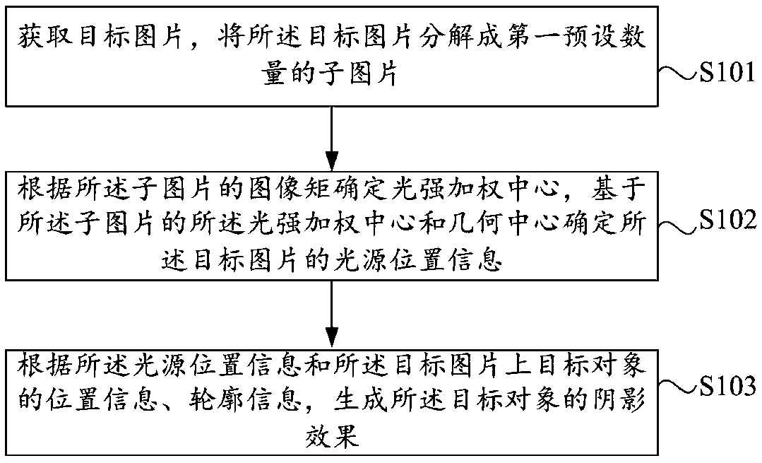
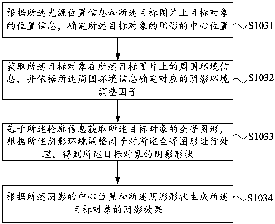
The embodiment of the invention provides a method and a device for determining a shadow effect, and an electronic device. The method comprises the following steps: obtaining a target picture, and decomposing the target picture into a first preset number of sub-pictures; determining a light intensity weighting center according to an image moment of the sub-picture, and determining light source position information of the target picture based on the light intensity weighting center and the geometric center of the sub-picture; generating a shadow effect of the target object according to the lightsource position information, the position information of the target object on the target picture, and the contour information. Through the method, the device and the electronic device, the light source position in the picture can be accurately and conveniently obtained, and other first-related factors are considered in the process of generating the shadow effect of the virtual object, so that theshadow effect of the virtual object is more realistic, and the immersion feeling of the user is improved.

Description

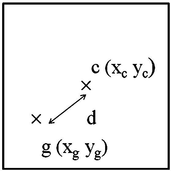
technical field [0001] The present invention relates to the technical field of image processing, in particular to a method, device and electronic equipment for determining shadow effects. Background technique [0002] Augmented Reality (AR) technology is a technology that calculates the position and angle of camera images in real time and adds corresponding images, videos, and 3D models to place virtual objects on the screen in the real world and interact with them. Users can perceive the existence of virtual objects by using AR devices. However, in the process of realizing the present invention, the inventor found that in related technologies, when rendering shadow effects on virtual objects, the shadow shape is generally only determined according to the shape of the virtual object, but in real scenes due to various factors The shape of the influence shadow generally has a certain deviation from its object body, which makes the shadow effect of the virtual object inconsist...

Claims


Application Information

Patent Timeline
Patent Type & Authority Applications(China)
IPC IPC(8): G06T15/60G06T19/00
CPCG06T15/60G06T19/006
Inventor 奥利维尔·菲永李建亿
Owner PACIFIC FUTURE TECH (SHENZHEN) CO LTD
Learn More