a terminal device

A terminal device and consistent technology, applied in the field of communication, can solve the problems of large size of terminal devices

Active Publication Date: 2021-01-08
VIVO MOBILE COMM CO LTD
View PDF13 Cites 0 Cited by
  • Summary
  • Abstract
  • Description
  • Claims
  • Application Information

AI Technical Summary

Problems solved by technology

[0003] An embodiment of the present invention provides a terminal device to solve the problem that the terminal device needs to provide an accommodation space for the millimeter wave antenna, so that the volume of the entire terminal device is relatively large

Method used


Image

  • a terminal device
  • a terminal device
  • a terminal device

Examples


Embodiment Construction

[0017] The following will clearly and completely describe the technical solutions in the embodiments of the present invention with reference to the accompanying drawings in the embodiments of the present invention. Obviously, the described embodiments are some of the embodiments of the present invention, but not all of them. Based on the embodiments of the present invention, all other embodiments obtained by persons of ordinary skill in the art without creative efforts fall within the protection scope of the present invention.

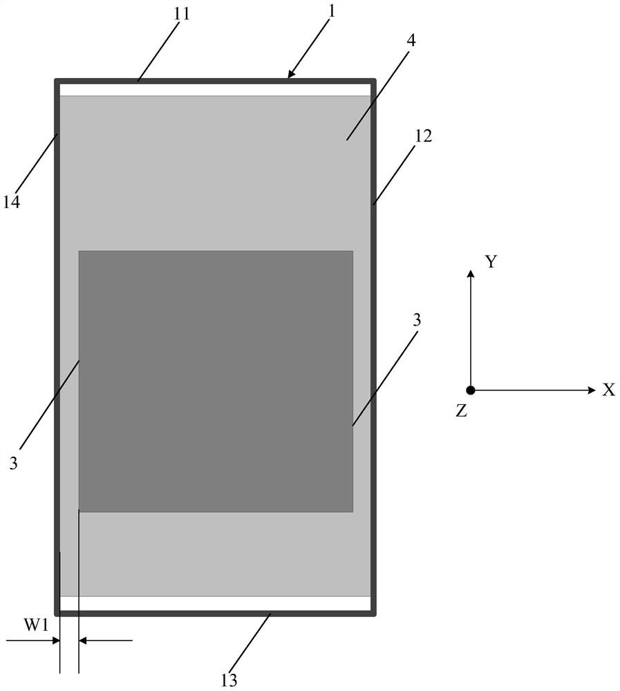
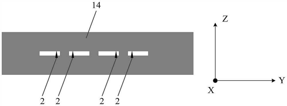
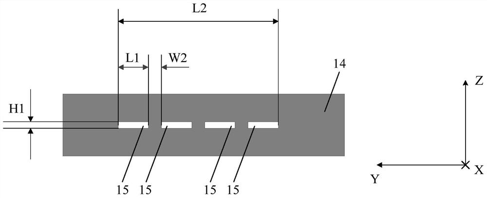
[0018] see figure 1 , figure 1 is a schematic structural diagram of a terminal device provided by an embodiment of the present invention, such as figure 1 As shown, it includes a metal frame 1, at least two slits 15 are opened on one side of the metal frame 1, and at least two antenna feed points 2 are arranged on the inner side wall of the metal frame 1, and the at least two antenna feed points Different antenna feed points 2 in the electric point 2...


PUM


Abstract

The present invention provides a terminal device. The terminal device includes a metal frame. At least two slits are opened on one side of the metal frame. At least two antenna feed points are provided on the inner wall of the metal frame. At least two antenna feed points Different antenna feeding points are located on the sides of different slots; there is also a signal reflection wall in the terminal equipment, and there is a gap between the signal reflection wall and at least two slots, and the signal reflection wall is formed by the metal outer wall of the battery of the terminal equipment; the metal Both the frame and the signal reflection wall are electrically connected to the floor inside the terminal equipment. In this way, the metal frame with gaps is equivalent to the millimeter-wave array antenna of the terminal device, and the metal frame is also the radiator of the communication antenna, thereby saving the accommodation space of the millimeter-wave antenna, reducing the volume of the terminal device, and It better supports the design of metal appearance, and can be compatible with the design of other antennas that use metal appearance to improve the overall competitiveness of terminal equipment.

Description

technical field [0001] The present invention relates to the technical field of communications, and in particular to a terminal device. Background technique [0002] With the rapid development of communication technology, multi-antenna communication has become the mainstream and future development trend of terminal equipment, and in the process, millimeter wave antennas are gradually introduced into terminal equipment. In the prior art, the millimeter wave antenna is generally in the form of an independent antenna module, so it is necessary to provide an accommodating space for the independent antenna module in the terminal device. In this way, the size of the entire terminal device is relatively large, resulting in relatively low overall competitiveness of the terminal device. Contents of the invention [0003] An embodiment of the present invention provides a terminal device, so as to solve the problem that an accommodation space for a millimeter wave antenna needs to be...

Claims


Application Information

Patent Timeline
Patent Type & Authority Patents(China)
IPC IPC(8): H01Q1/36H01Q1/44H01Q1/48H01Q1/50H01Q19/10H01Q19/12H01Q21/00
CPCH01Q1/36H01Q1/44H01Q1/48H01Q1/50H01Q19/10H01Q19/12H01Q21/0006H01Q13/10H01Q19/17H01Q21/08H01Q1/243
Inventor 王义金黄奂衢简宪静
Owner VIVO MOBILE COMM CO LTD
Why Eureka
Try Eureka