Brushless DC motor lead wire needle guard seat structure and brushless DC motor thereof

A brushless DC motor, lead pin technology, applied in electrical components, electromechanical devices, electric components, etc., can solve the problems of installation method error, lead pin bending, affecting production, etc., to ensure the effect of normal wiring

Pending Publication Date: 2018-12-11
常州市永安电机厂有限公司
View PDF0 Cites 0 Cited by
  • Summary
  • Abstract
  • Description
  • Claims
  • Application Information

AI Technical Summary

Problems solved by technology

[0003] A coil is wound on the stator frame of the motor. When the motor is started, the coil needs to be energized. The lead wire needle is used as an intermediate component connecting the coil and the external circuit, and the lead wire needle needs to be fixed on the stator frame. The installation method is to install it in the pin hole of the stator frame. Due to the error of the installation method, some lead pins will bend to one side. After the lead pin is installed in the pin hole, it is necessary to close the mold to fix the lower end of the lead pin. In order to prevent the upper end of the lead pin from sticking to the colloid and affect the subsequent wiring, the upper mold needs to seal the upper end of the lead pin. If the lead pin is bent, the upper mold will collide with the lead pin when it cooperates with the lead pin, causing the lead pin to bend, resulting in abnormal follow-up Wiring affects production

Method used


Image

  • Brushless DC motor lead wire needle guard seat structure and brushless DC motor thereof
  • Brushless DC motor lead wire needle guard seat structure and brushless DC motor thereof
  • Brushless DC motor lead wire needle guard seat structure and brushless DC motor thereof

Examples


Embodiment Construction

[0022] The present invention will be described in detail in conjunction with accompanying drawing now. This figure is a simplified schematic diagram only illustrating the basic structure of the present invention in a schematic manner, so it only shows the components relevant to the present invention.

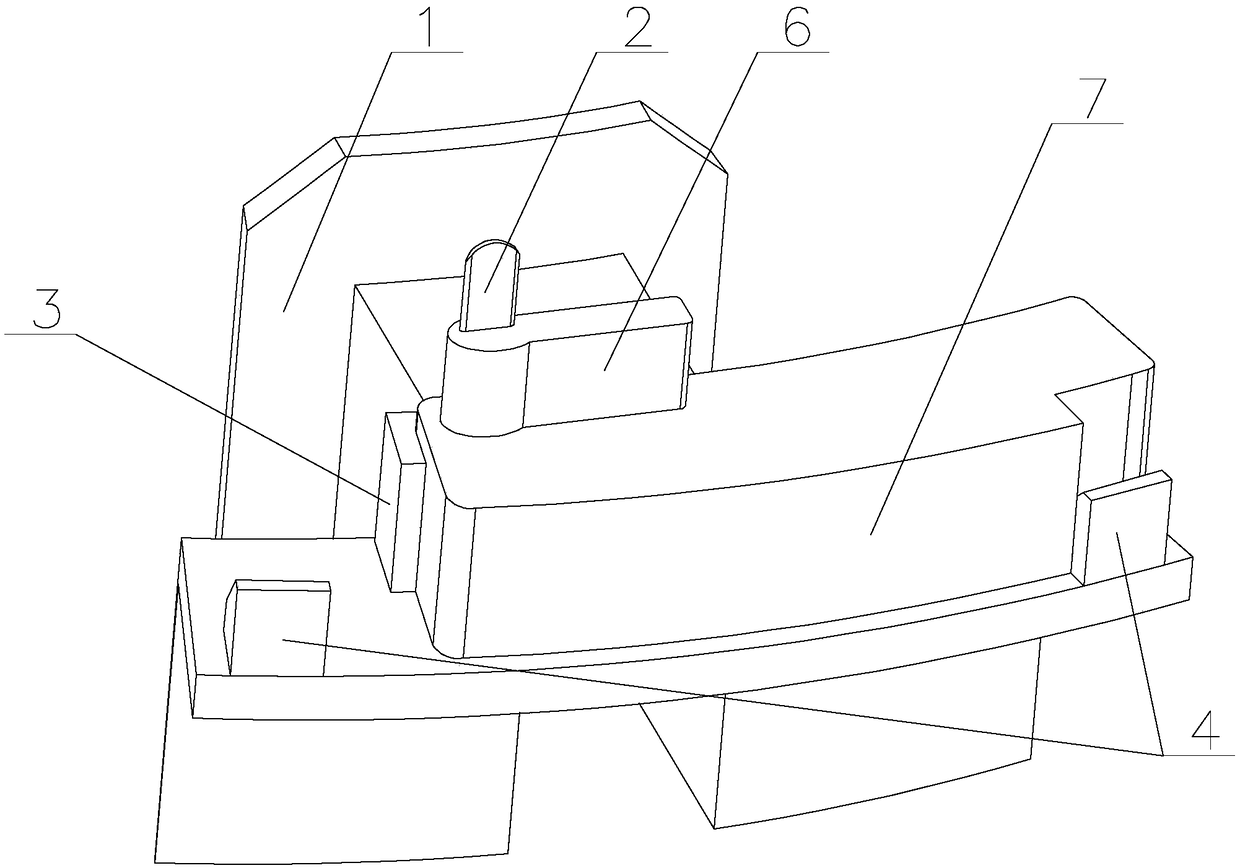
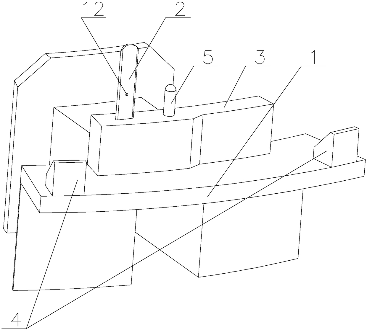
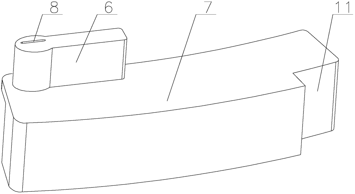
[0023] Such as Figure 1-5 As shown, a DC brushless motor wire needle guard seat structure of the present invention includes a skeleton 1, and the skeleton 1 is provided with a wire needle 2, a needle guard, a connecting block 3 and two correction blocks 4, the The upper end of the connection block 3 is provided with a pin hole, and one side of the pin hole is vertically provided with a limit column 5, and the limit column 5 is integrally processed with the connection block 3, and the correction block 4 is arranged on the Outside the connection block 3, a limit groove for limiting the position of the needle guard is provided between the correction block 4 and the connection blo...


PUM


Abstract

A DC brushless motor lead wire needle guard seat structure and its DC brushless motor are provided, The brushless DC motor lead wire needle guard seat structure includes a skeleton, A lead wire needle, a Needle protection sleeve, a connecting block and a rectifying block are arranged on the skeleton, a needle hole is disposed on the upper end of the connecting block, A limit column is vertically arranged on one side of the needle hole, The rectifying block is arranged on the outside of the connecting block, A limit groove for limiting that position of the needle guard sleeve is arranged between the rectifying block and the connecting block, The upper end surface of that rectify block is inclined downward from the outside to the inside, the low end of the lead pin is inserted into the neelde hole, the needle protecting sleeve comprises a plug block and a guide block, a rectify hole matched with the lead pin is vertically arranged on the plug block, a first guide groove is arranged on the inner side of the guide block, and a second guide groove is arranged on the outer side of the guide block. The invention adopts needle protecting sleeve, the connecting block and the rectifying block which cooperate with each other to rectify the position of the lead needle which is bent forward and backward or left and right twisted into a vertical state, so as to ensure that the upper mold does not collide with the lead needle when the mold is closed and glued, and ensure the subsequent normal wiring.

Description

technical field [0001] The invention relates to the technical field of brushless motors, in particular to a brushless direct current motor lead wire needle guard seat structure and the brushless direct current motor. Background technique [0002] The brushless DC motor consists of a motor body and a driver, and is a typical mechatronic product. Since the brushless DC motor operates in a self-controlled manner, it does not add an additional starting winding to the rotor like a synchronous motor with heavy load under variable frequency speed regulation, nor does it cause oscillation and out of step when the load changes suddenly. The permanent magnets of brushless DC motors with small and medium capacity are now mostly made of rare earth neodymium iron boron (Nd-Fe-B) materials with high magnetic energy levels. Therefore, the volume of the rare earth permanent magnet brushless motor is reduced by one frame size compared with the three-phase asynchronous motor with the same ca...

Claims


Application Information

Patent Timeline
Patent Type & Authority Applications(China)
IPC IPC(8): H02K3/50
CPCH02K3/50
Inventor 徐仁荣
Owner 常州市永安电机厂有限公司
Why Eureka
Try Eureka