An intelligent lighting control system and method

A technology of intelligent lighting and control methods, applied in the direction of energy-saving control technology, light source, electric light source, etc., can solve the problems of no time division, light brightness adjustment, light control adjustment, etc., to reduce resource waste, save energy resources, and prolong life Effect

Inactive Publication Date: 2018-12-11
GUANGDONG UNIV OF TECH
View PDF6 Cites 15 Cited by
  • Summary
  • Abstract
  • Description
  • Claims
  • Application Information

AI Technical Summary

Problems solved by technology

[0002] In the traditional lighting control system, street lights, corridor lights and lights in public places are all kept on during the entire lighting period, and the lights are not controlled in consideration of the specific time, place and flow of people/vehicles At the same time, there is no time to adjust the brightness of the light, so the traditional lighting control system has a serious problem of high power cons

Method used


Image

  • An intelligent lighting control system and method
  • An intelligent lighting control system and method
  • An intelligent lighting control system and method

Examples


Embodiment 1

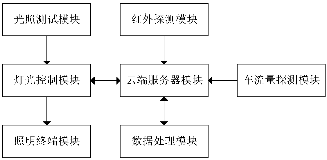
[0048] This embodiment provides an intelligent lighting control system, such as figure 1 As shown, the intelligent lighting control system includes: a lighting control module, an infrared detection module, a traffic flow detection module, a lighting test module, a cloud server module, a data processing module and a lighting terminal module;

[0049] The lighting terminal module and the lighting test module are respectively connected to the lighting control module, the lighting control module, the infrared detection module and the traffic flow detection module are connected to the cloud server module through the network, and the cloud server module is connected to the data processing module;

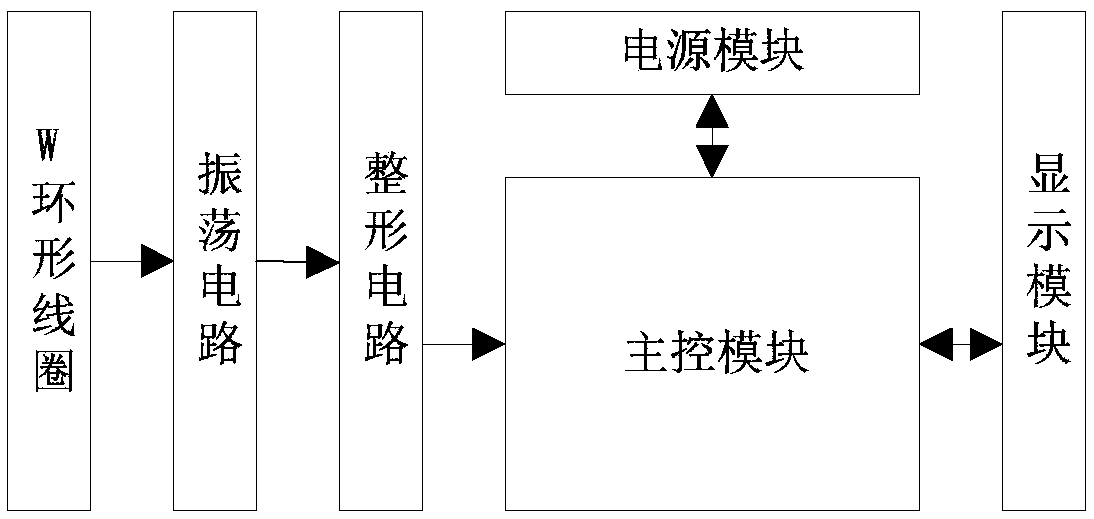
[0050] The infrared detection module includes a power supply module, an infrared detector and a human flow detection module, and the power supply module and the infrared detector are respectively electrically connected to the human flow detection module;

[0051] The infrared sensor is th...

Embodiment 2

[0056] Based on the intelligent lighting control system, this embodiment provides an intelligent lighting control method, including the following steps:

[0057] S1: Through the infrared detection module and the traffic flow detection module, the traffic flow and traffic flow data of different time periods are detected and transmitted to the cloud server module for storage;

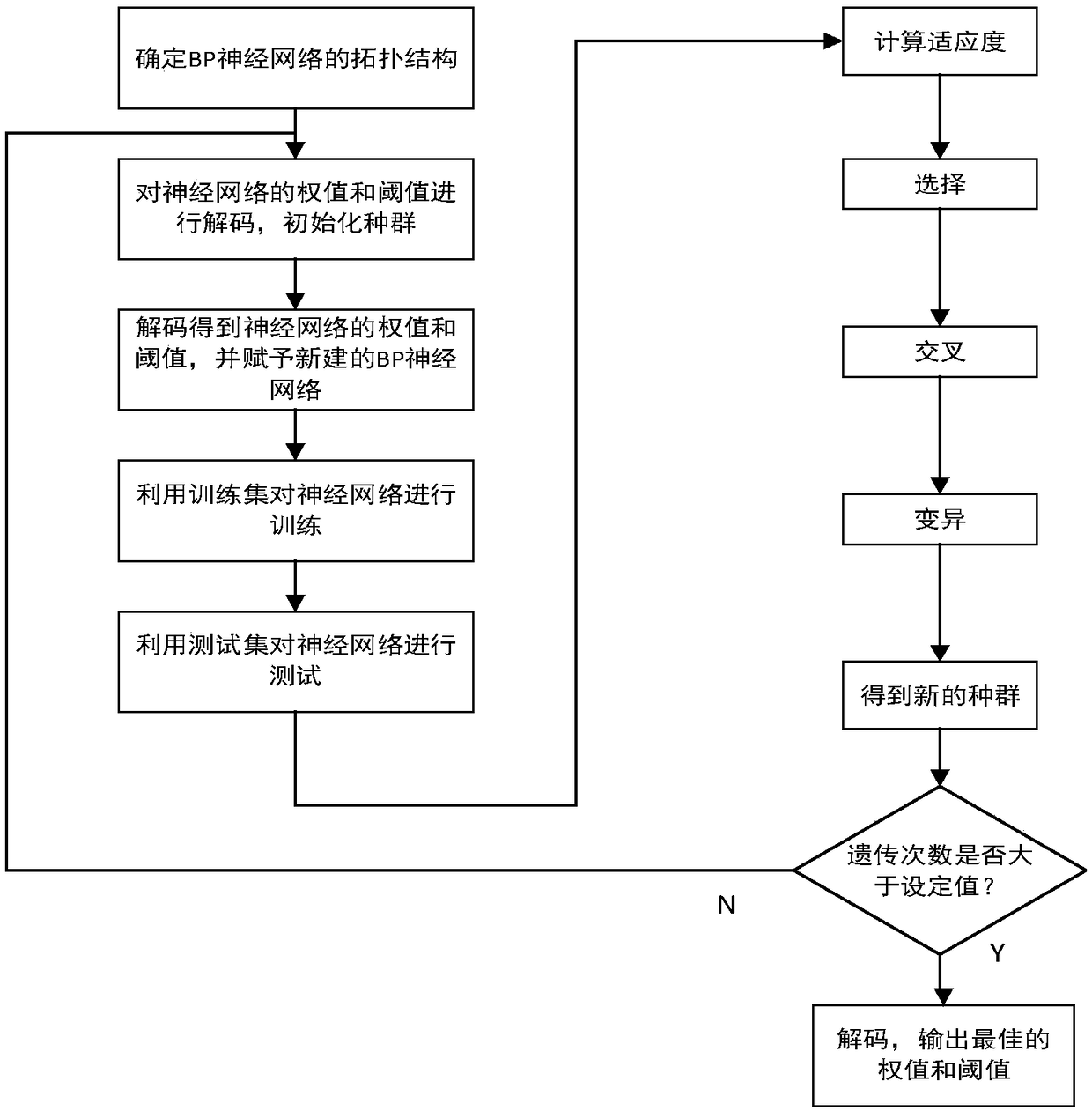
[0058] S2: The data processing module reads the data of the flow of people and traffic detected by the infrared detection module and the traffic detection module from the cloud server module, and then puts these data into the BP neural network corrected based on the genetic algorithm for training, Predict the flow of people / vehicles at each time period in the future, and upload the prediction results of the flow of people / vehicles to the cloud server module for storage;

[0059] S3: The lighting control module reads the predicted results of people / vehicle flow stored in the remote server through the netwo...


PUM


Abstract

The invention provides an intelligent lighting control system and method thereof. The system comprises a lighting control module, an infrared detection module, a vehicle flow detection module, a lighting test module, a cloud server module, a data processing module and a lighting terminal module. The method detects pedestrian flow and vehicle flow data transmission in different time periods throughan infrared detection module and a vehicle flow detection module to be stored in a cloud server module, the data processing module reads data from the cloud server module, puts the data into the BP neural network corrected based on the genetic algorithm for training, predicts the person/vehicle flow in each period of the future day, and uploads the obtained person/vehicle flow prediction result to the cloud server module for storage, The lighting control module determines the adjustment of the lighting brightness according to the data prediction result and the lighting intensity detected by the lighting test module, and then controls the lighting terminal module to realize the lighting effect of different modes.

Description

technical field [0001] The present invention relates to the field of intelligent lighting control, and more specifically, to an intelligent lighting control system and method. Background technique [0002] In the traditional lighting control system, street lights, corridor lights and lights in public places are all kept on during the entire lighting period, and the lights are not controlled in consideration of the specific time, place and flow of people / vehicles At the same time, there is no division of time to adjust the brightness of the light, so the traditional lighting control system has a serious problem of high power consumption. [0003] At present, most of the lighting systems often do not realize the functions of self-starting according to the intensity of natural light, adjusting the brightness of the light according to different time periods, and controlling the brightness of the light and the switch in real time according to the flow of people / vehicles to realiz...

Claims


Application Information

Patent Timeline
IPC IPC(8): H05B37/02
CPCH05B47/105H05B47/11Y02B20/40
Inventor 吴豪乐许锐许锦标
Owner GUANGDONG UNIV OF TECH
Why Eureka
Try Eureka