Bubble resistance-reduction impeller and cleaning machine comprising same
A cleaning machine and wave blocking technology, applied in the field of cleaning machines, can solve the problems of limited cleaning ability of pulsator, and achieve the effect of improving cleaning ability and improving flushing effect.
- Summary
- Abstract
- Description
- Claims
- Application Information
AI Technical Summary
Problems solved by technology
Method used
Image

Examples
Embodiment 1
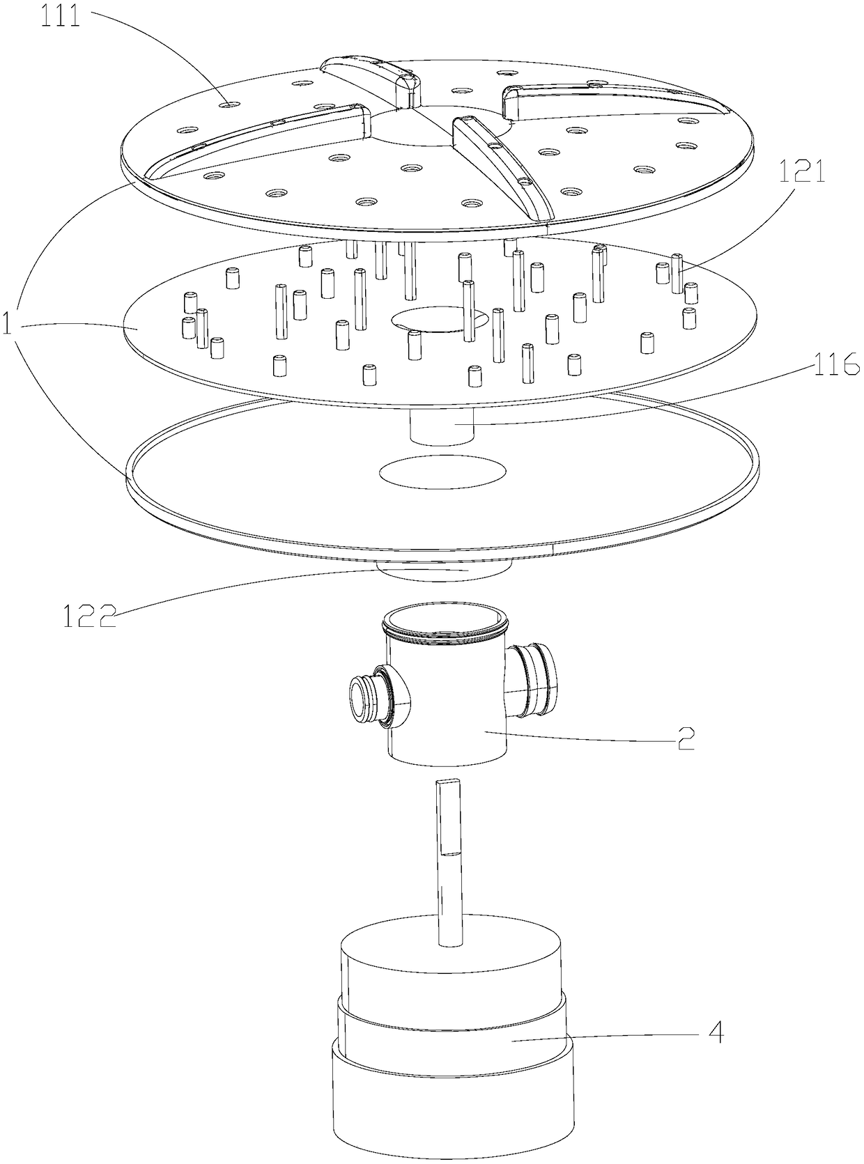
[0039] Please refer to attached figure 1 To attach image 3 , attached Figure 12 , in an embodiment of the present invention, a cleaning machine, a bubble drag reducing pulsator, a washing machine tank 3, an air pump, a water pump, and a drive motor 4, the bubble drag reducing pulsator includes a pulsator body 1, and the air bubble drag reducing pulsator The pulsator body 1 is rotatably arranged at the bottom of the water tank 3 of the washing machine, the lower end of the pulsator body 1 passes through the bottom of the water tank 3 of the washing machine, the air pump and the water pump are connected with the pulsator body 1 respectively, and the driving motor 4 can drive the pulsator body 1 to rotate . The cleaning machine of the present invention can be a vegetable washing machine or a dishwasher or other types of cleaning machines, the gas phase fluid can be air input through an air pump, and the liquid phase fluid can be water input through a water pump.
[0040] Ple...
Embodiment 2
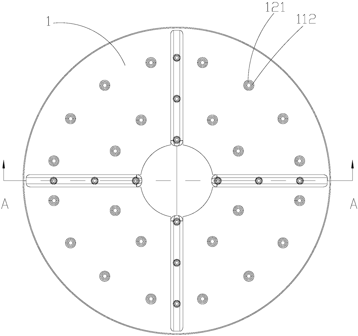
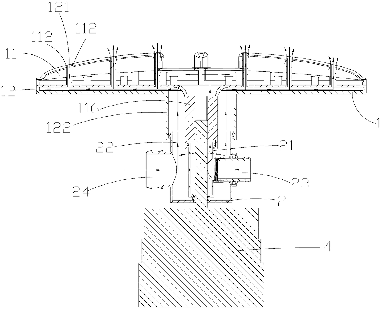
[0045] Please refer to attached Figure 4 To attach Figure 8 The difference between this embodiment and Embodiment 1 is that the inner wall of the first through hole 111 on the first cavity 11 is formed to extend inward and block the gap 112 between the inner wall of the first through hole 111 and the outer wall of the hollow tube 121. The sealing end face is provided with several second through holes 113 communicating with the first cavity 11, the fluid in the first cavity 11 is ejected from the upper end of the first cavity 11 through the second through holes 113, and the second through hole 113 The fluid in the second cavity 12 is ejected from the upper end of the first cavity 11 through the hollow tube 121 .
Embodiment 3
[0047] The difference between this embodiment and Embodiment 2 is that a sealing end surface is formed at the opening of the upper end of the hollow tube 121, and several third through holes are arranged on the sealing end surface, and the fluid in the second cavity 12 passes through the third through holes. The hole is ejected from the upper end of the first cavity 11 , and the fluid in the first cavity 11 is ejected from the upper end of the first cavity 11 through the second through hole 113 .
PUM
 Abstract
Description
Claims
Application Information
PatSnap Eureka turns technology decisions into work you can execute. Powered by our Innovation Knowledge Graph, it runs expert workflows across engineering, life sciences, materials and intellectual property. Get your review-ready output in minutes.


