
Drawing mechanism

A technology of depth and mold components, which is applied in the direction of metal processing equipment, forming tools, manufacturing tools, etc., can solve the problems of unfavorable material forming performance and stability of stripping, and achieve good drawing performance, stable stripping process, and increased The effect of longevity

Pending Publication Date: 2018-12-14
苏州瑞玛精密工业股份有限公司
View PDF0 Cites 1 Cited by
  • Summary
  • Abstract
  • Description
  • Claims
  • Application Information

AI Technical Summary

Problems solved by technology

[0002] In the stamping field, the continuous drawing die is a common type of die, and the drawing ring is an indispensable part for drawing. How to design the shape of the drawing ring reasonably has a great influence on the drawing mechanism, the life and stability of the drawing ring Important influence, the forming area of ​​the traditional deep drawing ring is generally followed by a taper angle, this kind of deep drawing ring is not conducive to the development of the material forming performance and the stability of the stripping

Method used


Image

  • Drawing mechanism
  • Drawing mechanism
  • Drawing mechanism

Examples

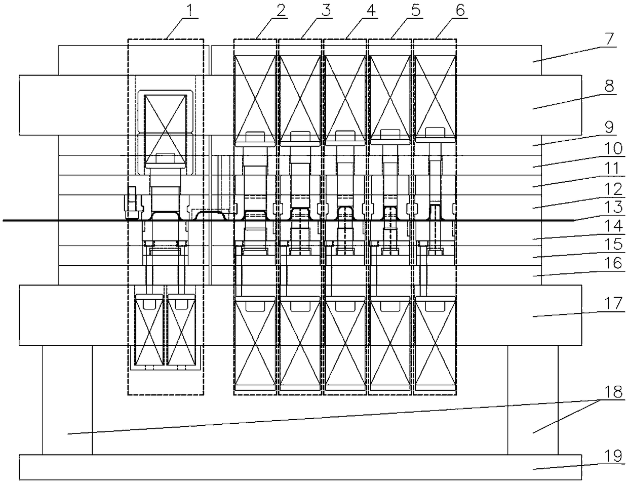
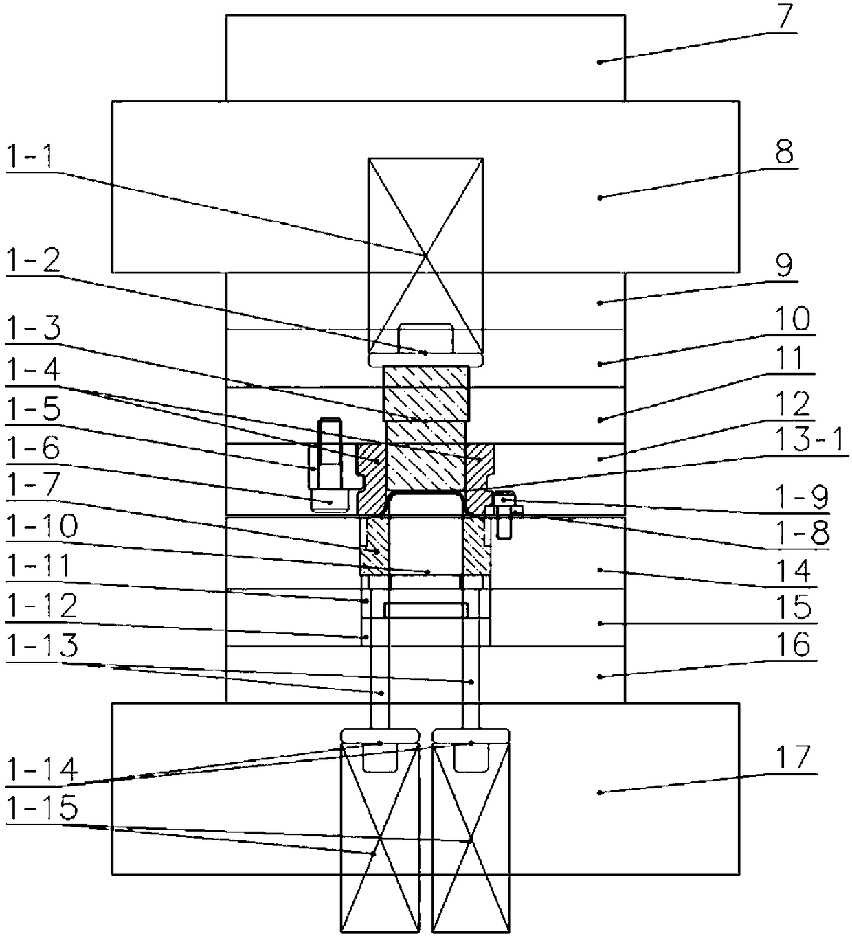
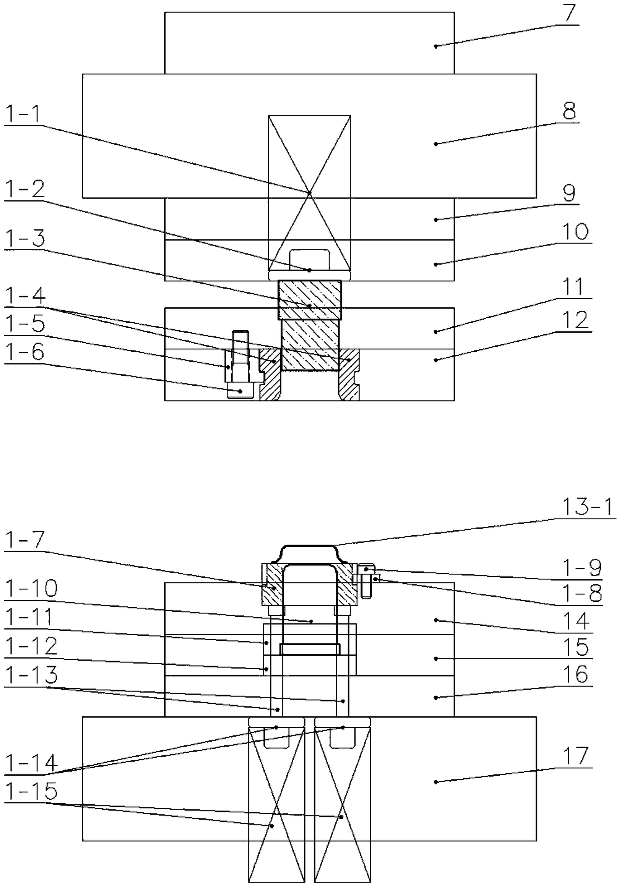

Embodiment Construction

[0024] The present invention will be further described below in conjunction with the examples shown in the drawings.

[0025] The drawing mechanism is used to deepen the plate into a product with a cylindrical groove. The groove is cylindrical and has a certain depth and inner diameter. The drawing mechanism includes an upper mold assembly, a lower mold assembly, and a The drawing parts in the upper film assembly and the lower die assembly, each of the drawing parts includes an upper drawing assembly and a drawing drawing assembly respectively provided in the upper die assembly and the lower die assembly, each The upper drawing assembly includes an upper mold stripping mechanism arranged in the upper mold assembly and a drawing ring sleeved on the upper mold stripping mechanism and fixed in the upper mold assembly. There is a deep-drawn fillet connecting area with an arc transition between the lower end surface of the deep ring and its inner side wall. The inner side wall from th...


PUM


Abstract

The invention discloses a drawing mechanism. The drawing mechanism comprises an upper mold assembly, a lower mold assembly and drawing parts, each drawing part comprises an upper drawing assembly anda lower drawing assembly, wherein the upper drawing assembly and the lower drawing assembly are arranged in the upper mold assembly and the lower mold assembly respectively, the upper drawing assemblies comprise upper mold stripping mechanisms arranged in the upper mold assembly and drawing rings which are arranged on the upper mold stripping mechanisms in a sleeving mode and fixedly arranged in the upper mold assembly, inner holes of the drawing rings are provided with arc-shaped transition drawing circular bead connecting regions, the inner side walls of the drawing rings are upwards and sequentially provided with straight barrel-shaped forming regions, stripping circular bead regions extending towards the outer side in an arc shape, straight wall regions with diameters larger than thoseof the forming regions, first circular bead connecting regions extending towards the inner side in an arc shape and stripping ejector rod matching regions extending towards the outer side in an arc shape from the arc-shaped transition drawing circular bead connecting regions. According to drawing mechanism, drawing performance is guaranteed to come into play better, processing technology of stripping rods is simplified, service life of the drawing rings is prolonged, a stripping process is made to be more stable, and the drawing mechanism is suitable for being widely popularized and used.

Description

Technical field [0001] The invention relates to a pressure riveting device, in particular to a drawing mechanism. Background technique [0002] In the stamping field, continuous drawing die is a common type of die, among which the drawing ring is an indispensable drawing part. How to design the shape of the drawing ring reasonably will affect the drawing mechanism, the life and stability of the drawing ring. Importantly, the traditional deep-drawing ring is generally followed by a cone angle behind the forming area. This kind of deep-drawing ring is not conducive to the development of the material's forming performance and the stability of the stripping. Therefore, we designed a new deep drawing ring structure and corresponding deep drawing mechanism. . Summary of the invention [0003] The purpose of the present invention is to provide a drawing mechanism that simplifies the processing technology of the stripping rod, increases the life of the drawing ring, and makes the stripp...

Claims


Application Information

Patent Timeline
Patent Type & Authority Applications(China)
IPC IPC(8): B21D22/22B21D37/10B21D45/04
CPCB21D22/22B21D37/10B21D45/04
Inventor 吴永丰陈晓敏朱纯傲戴小祥马驰任军平
Owner 苏州瑞玛精密工业股份有限公司
Learn More