Rubber strip winding machine

A winding machine and rubber strip technology, which is applied in the direction of winding strips, thin material processing, transportation and packaging, etc., can solve the problem of rubber strip tearing, avoid breakage, improve winding efficiency, and improve pass rate Effect

Pending Publication Date: 2018-12-14
JIAXING CHUANQI MECHANICAL EQUIP CO LTD
View PDF0 Cites 3 Cited by
  • Summary
  • Abstract
  • Description
  • Claims
  • Application Information

AI Technical Summary

Problems solved by technology

However, during the working process of the winding motor, as the diameter of the winding reel gradually increases, t

Method used


Image

  • Rubber strip winding machine
  • Rubber strip winding machine
  • Rubber strip winding machine

Examples


Embodiment Construction

[0015] The rubber strip winder of the present invention will be further described in detail in conjunction with the accompanying drawings and specific embodiments:

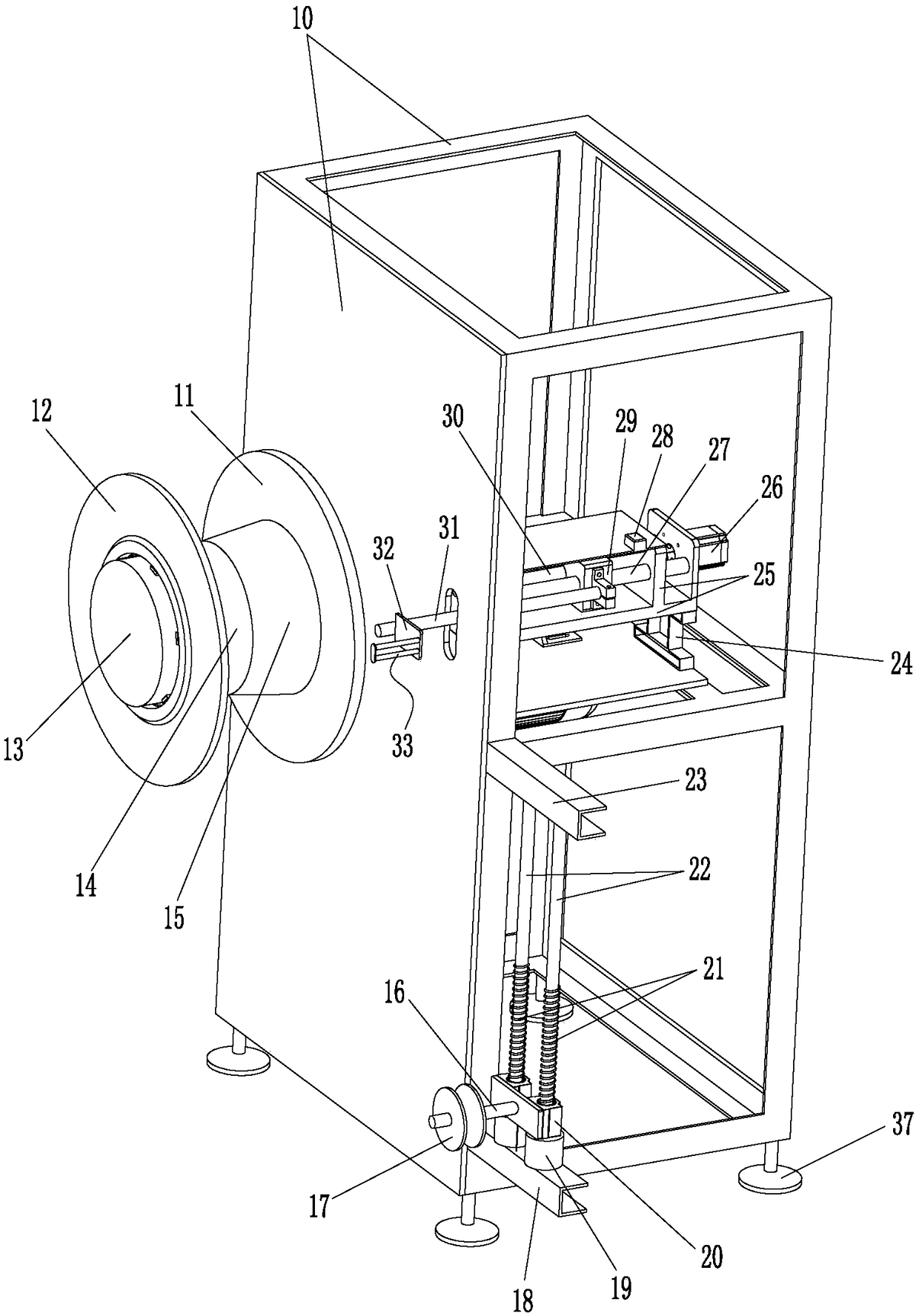
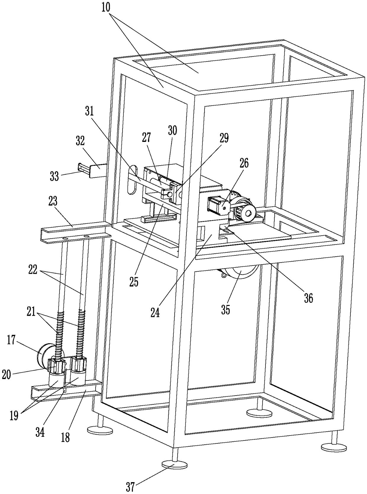
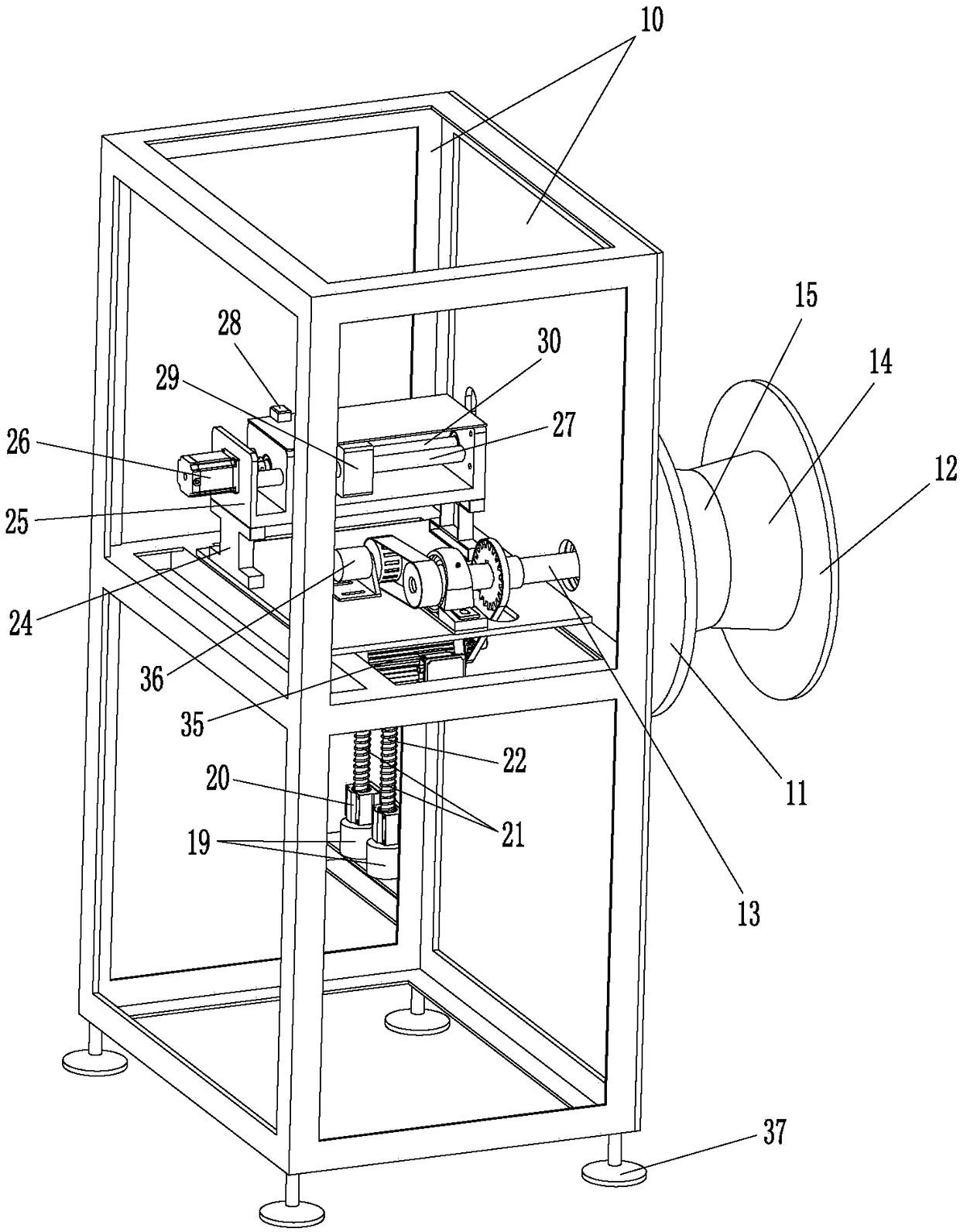
[0016] Such as figure 1 , figure 2 and image 3 As shown, in this specific embodiment, the rubber strip winding machine of the present invention includes a frame 10, a winding shaft 13, a winding motor 35 for driving the winding shaft 13 to rotate, and four bottoms installed at the bottom of the frame 10. Pin 37 also includes guide wheel 17, backguy sensor 34, sliding sleeve 20, guide rod 22, guide roller 33, support rod 31, slide block 29, guide rail 27, reset sensor 28, support seat 25, base 24, screw mandrel 30 and the stepper motor 26 used to drive the slider 29 to slide back and forth along the guide rail 27.

[0017] Rewinding shaft 13 is horizontally installed on the top of frame 10 by bearing and bearing seat, and winding motor 35 is contained in the afterbody of winding shaft 13, is connected with win...


PUM

PropertyMeasurementUnit
Angleaaaaaaaaaa

Abstract

The invention discloses a rubber strip winding machine. The rubber strip winding machine comprises a rack, bottom studs, a winding shaft, a winding motor, a guiding wheel, a pulling wire sensor, sliding sleeves, guiding rods, guiding rollers, a supporting rod, a sliding block, two guide rails, a reset sensor, a supporting base, a base, a lead screw and a stepping motor; the guiding rods which arevertically arranged are located on the feeding side of the winding shaft and installed on the lower portion of the side wall of the rack through U-shaped channel steel; the sliding sleeves are vertically and slidably connected with the guiding rods; a pulling rope of the pulling wire sensor is connected with the sliding sleeve; the guiding rollers are located between the winding shaft and the guiding wheel, arranged on the upper portion of the rack and installed on the front portion of the supporting rod; the back portion of the supporting rod penetrates through the rack and is connected withthe sliding block; the sliding block is arranged on the two guide rails in a sleeving mode; the ends of the guide rails are installed on the supporting base; the supporting base is installed on the rack through the base; and the stepping motor is installed at the tail of the supporting base, a rotation shaft of the stepping motor is connected with the lead screw, and the lead screw is in threadedconnection with the sliding block. According to the rubber strip winding machine, in the whole winding process of rubber strips, stress equilibrium of the conveyed rubber strips can be always kept, and the fracture phenomenon can not be generated.

Description

technical field [0001] The invention relates to equipment for winding and packaging produced rubber strips, in particular to a rubber strip winding machine. Background technique [0002] Rubber is one of the raw materials commonly used in industrial production and is widely used in various industries. [0003] After the rubber strip is processed and formed, it needs to be rolled up to facilitate subsequent transportation and storage. At present, the structure of the equipment used to rewind the rubber strip is usually very simple. There is only one frame, and the rewinding motor and the rewinding shaft are installed on the frame; when working, the winding motor drives the rotation of the rewinding shaft to realize Rewinding of rubber strips. However, during the working process of the winding motor, as the diameter of the winding reel gradually increases, the pulling force on the conveyed rubber strip is also increasing, and the rubber strip is easily torn off. Contents o...

Claims


Application Information

Patent Timeline
IPC IPC(8): B65H18/10B65H18/02B65H23/198
CPCB65H18/10B65H18/02B65H23/198B65H2701/19
Inventor 王海斌
Owner JIAXING CHUANQI MECHANICAL EQUIP CO LTD
Why Eureka
Try Eureka