Al technical title is built by PatSnap Al team. It summarizes the technical point description of the patent document.
A buffer device and deceleration device technology, applied in transportation and packaging, lifting equipment in mines, etc., can solve problems such as cage falling speed or acceleration exceeding, safety accidents, falling out of control, etc., to achieve reliable work, high safety performance, and design simple effect
Inactive Publication Date: 2018-12-14
CHINA UNIV OF MINING & TECH (BEIJING)
View PDF4 Cites 5 Cited by
Summary
Abstract
Description
Claims
Application Information
AI Technical Summary
This helps you quickly interpret patents by identifying the three key elements:
Problems solved by technology
Method used
Benefits of technology
Problems solved by technology
In production operations, it often happens that the falling speed or acceleration of the cage exceeds the standard specification requirements caused by various reasons, which eventually leads to loss of control and safety accidents
Method used
Image
Click on the blue label to locate the original text in one second.
Reading with bidirectional positioning of images and text.
Examples
Embodiment Construction
[0015] The present invention will be further described below in conjunction with accompanying drawings and examples of implementation.
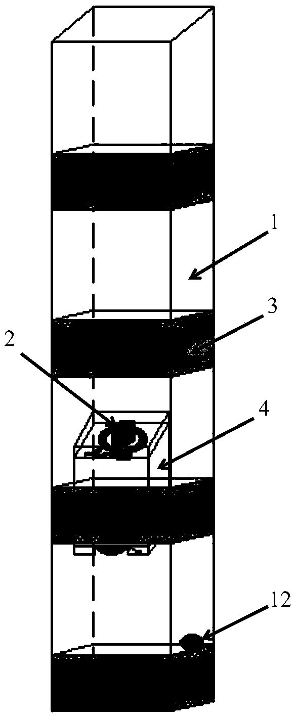
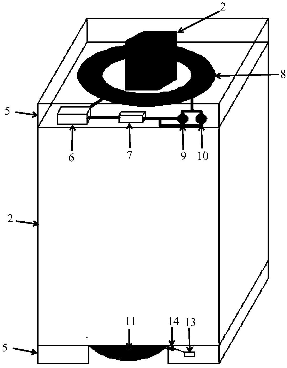
[0016] An anti-falling deceleration buffer device for a cage is composed of an electromagnetic induction deceleration device and an auxiliary inflatable buffer device. Among them, the electromagnetic induction deceleration device is composed of an aluminum plate ring 3, a power supply 6, a resistor 7, an electric coil 8, a speed sensor 9, and an acceleration sensor 10; the auxiliary inflatable buffer device is composed of an airbag 11, a proximity switch 12, a trigger 13, and an igniter 14 composition.
[0017] Add a fixed width of 5m and a thickness of 1cm aluminum ring 3 every 10m on the tank road 1. The aluminum ring 3 can reinforce the tank road 1; , the speed sensor 9 and the acceleration sensor 10 are arranged in the protective shell 5, the electric coil 8 is connected to the power supply 6 and the resistor 7, and the speed sensor 9 an...
PUM
Abstract
The invention relates to a cage anti-falling speed reduction buffer device. The cage anti-falling speed reduction buffer device is composed of an electromagnetic induction speed reduction device and an auxiliary inflatable buffer device; an aluminum plate ring is fixed on a cage channel, when the cage falls, a speed sensor or an acceleration sensor exceeds a specified maximum value, automatic circuit conduction is achieved on the speed sensor or the acceleration sensor, the strong current generates a strong magnetic field, according to the Lenz's law, when the cage passes through the aluminumplate ring, the magnetic field of the induced current is always used for blocking the change of the magnetic flux of the induced current, the generated resistance enables the cage to achieve speed reduction to be descended, the cage is descended safely through the step type speed reduction, the safety of the personnel is guaranteed, and the first protection effect is achieved; and a proximity switch enables a trigger to act, the current is sent to an igniter, the sodium nitride propellant contained in the igniter is ignited, then a large amount of harmless gas which takes nitrogen as a main gas can be generated, an air bag is inflated to a full state, and a second protection effect is achieved. According to the cage anti-falling speed reduction buffer device, the design is simple, the weight of the cage cannot be increased, the long-standing technical problem that the cage falls due to the facts that the case suffers from rope breakage, failed braking and failure of an anti-falling device are solved, the work is reliable, the safety performance is high, and the practicability is high.
Description
technical field [0001] The invention relates to a cage anti-falling deceleration buffer device, which belongs to the technical field of shaft engineering, and in particular to a cage anti-falling deceleration buffer device in shaft shaft equipment. Background technique [0002] Cage is one of the important equipment in mine hoisting, used to transport personnel, ore and materials, etc. Its normal operation is of great significance to the safe production of mining enterprises. Due to loose ropes, broken ropes, failure of the braking system, failure of protective devices such as fall arresters, and other reasons, tanks may fall, which may damage the wellbore equipment at the slightest level, resulting in suspension of production for maintenance, and at the worst, bring harm to the personal safety of the miners. had serious consequences. At present, the rail tank track fall arrester uses the steel rail tank track as the supporting element of the fall arrester. When the hoistin...
Claims
Application Information
Patent Timeline
Application Date:The date an application was filed.
Publication Date:The date a patent or application was officially published.
First Publication Date:The earliest publication date of a patent with the same application number.
Issue Date:Publication date of the patent grant document.
PCT Entry Date:The Entry date of PCT National Phase.
Estimated Expiry Date:The statutory expiry date of a patent right according to the Patent Law, and it is the longest term of protection that the patent right can achieve without the termination of the patent right due to other reasons(Term extension factor has been taken into account ).
Invalid Date:Actual expiry date is based on effective date or publication date of legal transaction data of invalid patent.