Reinforcement structure of building foundation and construction method thereof

A technology for strengthening structures and buildings, which is applied in the fields of basic structure engineering, basic structure repair, construction, etc., can solve the problems that the durability of steel pipe piles cannot be guaranteed, it is difficult to meet the design requirements, and the welding operation is difficult, etc., to achieve Ensure the effective grouting volume, improve durability and reduce the difficulty of construction operation

Active Publication Date: 2020-06-26
中核四达建设监理有限公司
View PDF5 Cites 0 Cited by
  • Summary
  • Abstract
  • Description
  • Claims
  • Application Information

AI Technical Summary

Problems solved by technology

[0004] However, the traditional pit-type static pressure pile top protection still has the following problems: 1. When steel pipe static pressure piles are used in self-weight collapsible loess foundations or large-thickness fill foundations, due to the large frictional resistance of the pile body (steel pipes), , the pile body must pass through the self-weight collapsible loess foundation or large-thickness fill layer to enter a better bearing layer, and the length of the pile body is often relatively long. When the pile pressure is insufficient, such as a small building with one or two floors The self-weight is too small, large-diameter steel pipe piles require a very large reaction force, etc., and the pile pressure construction is often very difficult to meet the design requirements; 2. The steel pipe piles have been buried in the foundation soil for a long time, and corrosion occurs. The rust problem makes the durability of the steel pipe pile not guaranteed; 3. When the steel pipe is welded, the end face is directly contacted and welded, the contact area is small, and the welding operation is difficult

Method used


Image

  • Reinforcement structure of building foundation and construction method thereof
  • Reinforcement structure of building foundation and construction method thereof
  • Reinforcement structure of building foundation and construction method thereof

Examples


Embodiment Construction

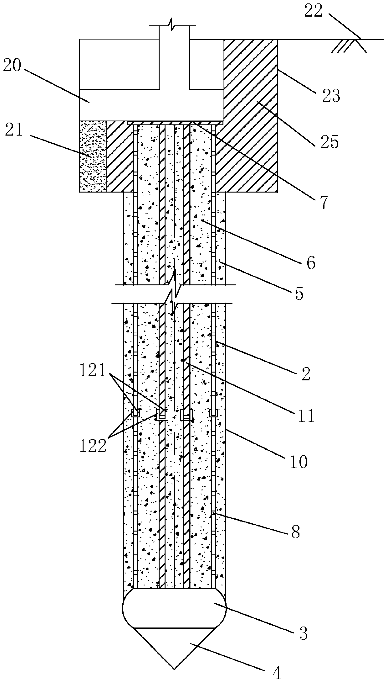
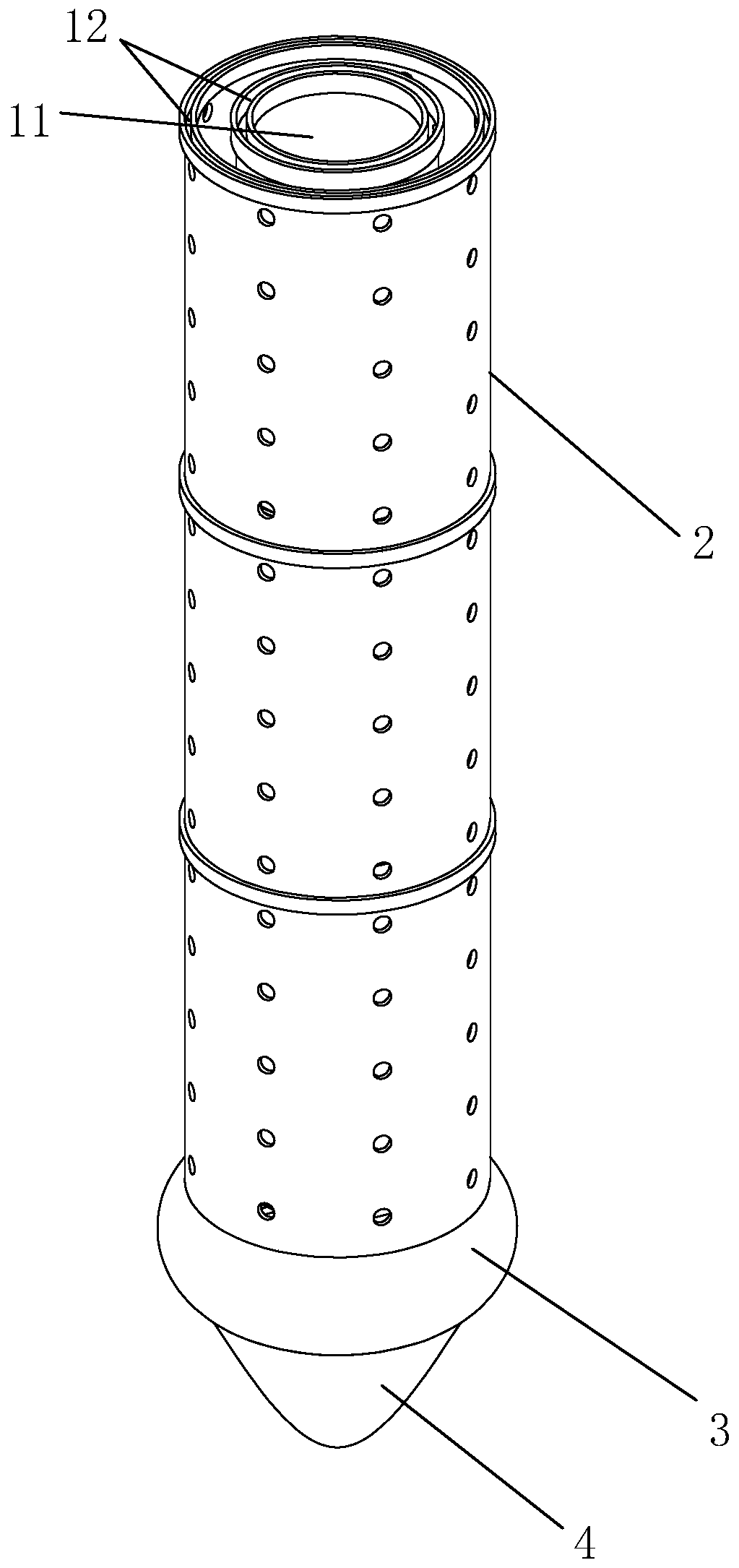
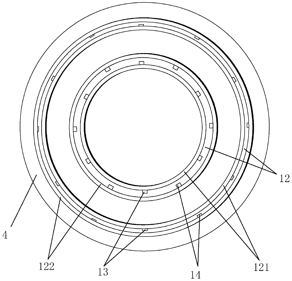
[0043] A reinforcement structure for building foundations, such as figure 1 and figure 2 As shown, it includes a static pressure pile welded from the end to the end of several steel pipes 11, a protective pipe 2 that is concentrically and vertically sleeved on the outside of each steel pipe 11 of the static pressure pile, and a thick middle section welded at the bottom of the static pressure pile and the protective pipe 2. And the upper and lower expansion parts 3, the pile head 4 smoothly welded on the bottom of the expansion part 3, the cement reinforcement layer 5 arranged between the protective pipe 2 and the surrounding soil layer 10, and the cement reinforcement layer 5 filled between the protective pipe 2 and the static pressure pile Cement protective layer 6. Concrete reinforcement slurry is poured into the steel pipe 11 forming the static pressure pile to obtain a static pressure pile with reinforcement filling, and the ends of several protective pipes 2 are welded ...


PUM


Abstract

The invention relates to the field of reinforcement of a building foundation and in particular relates to a reinforcement structure of the building foundation. The reinforcement structure comprises astatic pressure pile, a pile head and a cement reinforcing layer. A capacity expansion piece which is thick in the middle and thin in the top and the bottom is fixedly arranged between the static pressure pile and the pile head. The bottom end of the capacity expansion piece is integrated with the pile head and is smoothly connected with the pile head, and the top end of the capacity expansion piece is fixedly connected with the bottom end of the static pressure pile. The maximum cross section of the capacity expansion piece is larger than the cross section of the static pressure pile. The outer side of the static pressure pile is vertically sleeved with a protection tube, and the outer diameter of the protection tube is less than the maximum cross section of the capacity expansion piece.The inner diameter of the protection tube is larger than the cross section of the static pressure pile, so that cement slurry is poured into a cavity between the protection tube and the static pressure pile to form a cement protection layer. The invention further relates to a construction method for reinforcement by using the reinforcement structure. The construction method comprises the steps: after digging a pit, pressing a steel tube and the protection tube into the pit in a sectional type, then pouring the cement slurry into the steel tube and the protection tube, and finally pouring concrete into the reinforcement pit and backfilling to the ground to form a bearing platform. The reinforcement structure has the advantages that the construction operation difficulty is low, and the durability of the static pressure pile is improved.

Description

technical field [0001] The invention relates to the technical field of building foundation reinforcement, in particular to a building foundation reinforcement structure and a construction method thereof. Background technique [0002] The reasons for strengthening the foundation of existing buildings include insufficient bearing capacity of the foundation of the building, the impact of the construction of new adjacent buildings, the decline of the groundwater level, the quality of the pile foundation is not up to standard, the number of detection points in the foundation survey is small, and the analysis of the soil layer is wrong, etc. These factors cause building wall cracks, foundation settlement and other quality problems, so that the building cannot meet the functional requirements and seriously threaten the safety of users. If the existing buildings are torn down and rebuilt, huge funds will be wasted, which is very uneconomical in terms of economic benefits. The metho...

Claims


Application Information

Patent Timeline
Patent Type & Authority Patents(China)
IPC IPC(8): E02D37/00E02D7/20E02D5/38
CPCE02D5/38E02D7/20E02D37/00
Inventor 郑佳伟王艺放李治明
Owner 中核四达建设监理有限公司
Why Eureka
Try Eureka