

Novel electric fence
A fence and electricity technology, applied in fences, building types, buildings, etc., can solve the problems of damage to the property interests of relevant units, easy lodging of electric fences, inconvenient loading and unloading of electric fences, etc., to achieve good reusability and short construction time. , to avoid the effect of disassembly
- Summary
- Abstract
- Description
- Claims
- Application Information
AI Technical Summary
Problems solved by technology
Method used
Image

Examples
specific Embodiment 1
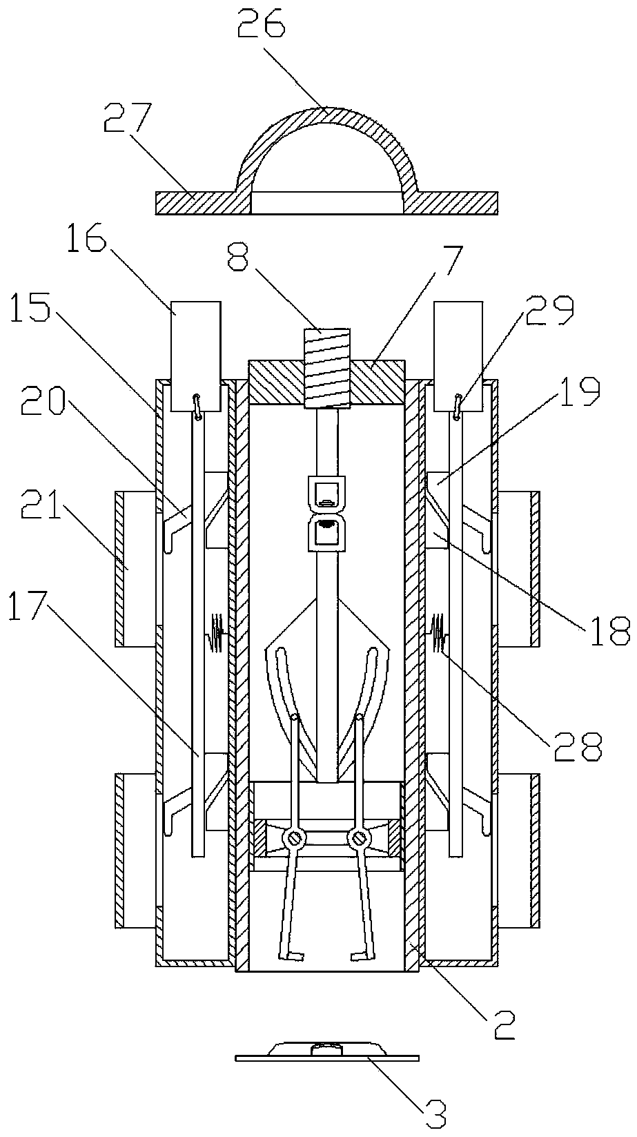
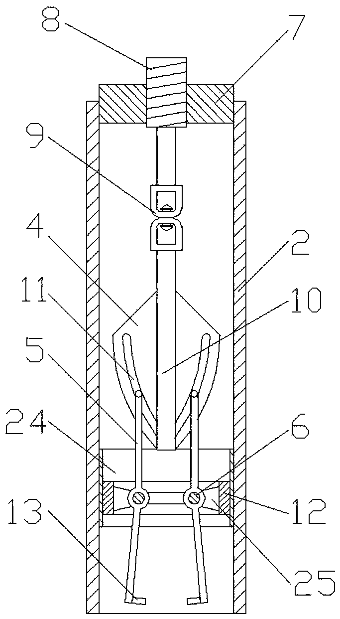
[0028] Specific embodiment 1, such as figure 1 and figure 2 As shown, the present invention is a new type of electric fence, including a fence pile and a fence body 1, and the fence pile includes a pile body 2 of a cylindrical structure and a fixed plate 3 arranged on the ground, and the pile body 2 A pile body locking mechanism that is detachably connected to the fixed disk 3 is provided inside, and the pile body locking mechanism includes a bolt telescopic mechanism, a limit slide plate 4, a locking swing arm 5 and a support ring 6, and the bolt body The telescopic mechanism includes a threaded ring 7 fixedly arranged on the upper end of the pile body 2, the inner ring hole of the threaded ring 7 is threadedly connected with a telescopic bolt 8, and the lower end of the telescopic bolt 8 is provided with a rotary connector 9, and the rotating The connector 9 is connected with the limit slide 4 by means of the lifting rod 10, and the limit slide 4 is provided with at least ...
specific Embodiment 2
[0031] Specific embodiment 2, further, the outside of the pile body 2 of the fence pile is also fixed with a fence locking mechanism, and the fence locking mechanism includes a fence lock sleeve 15, a push block 16 and a lock plate 17, The fence lock sleeve 15 has a cylindrical structure, the push block 16 and the lock plate 17 are arranged in the fence lock sleeve 15, and the lock plate 17 is vertically arranged in the fence lock sleeve 15, so that The upper end of the lock plate 17 is in contact with the lower end of the push block 16, and a wedge-shaped fixed slider 18 is also arranged in the described fence lock sleeve 15, and a wedge-shaped movable slider 19 is arranged on the back of the lock plate 17 to fix The sliding block 18 is set opposite to the wedge point of the moving slider 19, the front of the lock plate 17 is provided with a J-shaped deadbolt 20, and the side wall of the fence lock sleeve 15 is provided with a locking bolt 20 protruding out. A through hole, t...
specific Embodiment 3
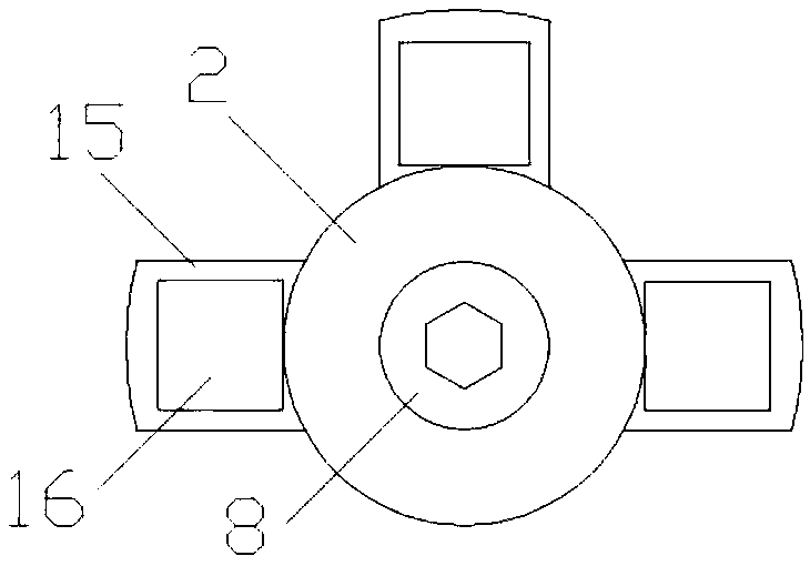
[0035] Specific embodiment 3, such as Image 6 As shown, the inner wall of the pile body 2 is provided with an auxiliary threaded sleeve 24 that cooperates with the support screw sleeve 12. 24 thread screw connection fixed.
[0036] A connecting piece 25 is arranged between the supporting screw sleeve 12 and the supporting ring 6 , and the supporting ring 6 and the supporting screw sleeve 12 are arranged coaxially by means of the connecting piece 25 .
[0037] Such as Image 6 , the structural schematic diagram of the cross-section of the pile body 2, it can be seen in the figure that the support ring 6 is fixed with the support screw sleeve 12 by means of the connecting piece 25, and the support screw sleeve 12 is fixed on the pile body 2 by means of the auxiliary threaded sleeve 24, so that the locking The force of the swing arm 5 can be finally transmitted to the pile body 2, so that the equipment can bear the force as a whole, avoiding the force applied by the locking sw...
PUM
 Abstract
Description
Claims
Application Information