Independently mounted hydrodynamic retarder

A hydraulic retarder and ventilation device technology, applied in the direction of liquid resistance brakes, slack adjusters, brake types, etc., can solve the problems of air leakage into the working chamber and affect the work of the hydraulic retarder, and reduce the number of replacements. The effect of oil frequency, light weight, and increased usability

Inactive Publication Date: 2018-12-14
NINGBO HUASHENG COMBINED BRAKE TECH CO LTD
View PDF0 Cites 2 Cited by
  • Summary
  • Abstract
  • Description
  • Claims
  • Application Information

AI Technical Summary

Problems solved by technology

When the oil in the fuel tank is pressed into the working cavity by high-pressure air, the hydraulic retarder works. When the high-pressure air in the fuel tank is discharged, the oil returns to the oil tank and the hydraulic retar

Method used


Image

  • Independently mounted hydrodynamic retarder
  • Independently mounted hydrodynamic retarder
  • Independently mounted hydrodynamic retarder

Examples


Embodiment 1

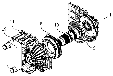
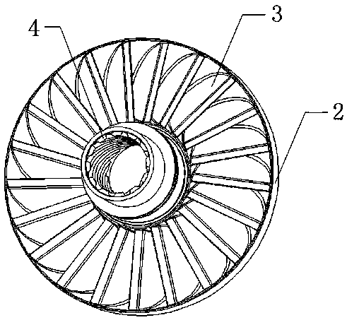
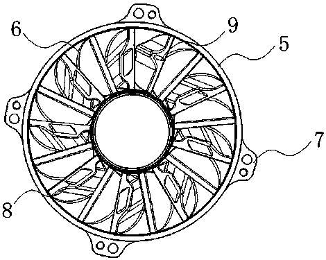
[0026] Such as Figure 1-6 As shown, the present invention discloses an independently installed hydraulic retarder, including a hydraulic retarder cover 1, a rotor pump driving wheel, a stator pump resistance wheel, a spline shaft 10, and a hydraulic retarder housing 11 , electromagnetic proportional valve 18 and heat exchanger 19, hydraulic retarder adopts hemispherical design, hydraulic retarder housing 11 includes working chamber 12 and oil storage chamber 13, hydraulic retarder cover 1 and hydraulic The retarder shells 11 are matched with each other and connected and fixed by fixing bolts. The stator pump resistance wheel is set in the working chamber 12 of the hydraulic retarder shell 11, and the rotor pump driving wheel is set in the hydraulic retarder cover 1. The key shaft 10 is arranged between the rotor pump driving wheel and the stator pump resisting wheel, and is driven to rotate by the thread structure. The ventilation device 16 is connected with the exhaust hole...


PUM


Abstract

The invention relates to the field of mechanical design and manufacturing, and discloses an independently mounted hydrodynamic retarder. The independently mounted hydrodynamic retarder comprises a hydrodynamic retarder cover, a rotor pump driving wheel, a stator pump driven wheel, a spline shaft, a hydrodynamic retarder shell, an electromagnetic proportional valve and a heat exchanger. By means ofoptimal structure design, the technology of separating the driving wheel and the driven wheel is adopted, and no-load loss generated when the retarder stops working is greatly reduced; and semi-spherical design is adopted by the overall appearance, stress is even, the heat radiating effect of the retarder is improved, and the use performance of the retarder is greatly improved. Aiming at the problem about medium oil recycling of an oil storage chamber of the retarder shell and overheating of the electromagnetic proportional valve, a corresponding solving design structure is provided, the oilreplacing frequency of the retarder is effectively reduced, and the heat exchange time of the retarder is effectively shortened; and the work efficiency is improved, cost is reduced, the service lifeof the retarder is prolonged, and the performance of the retarder is improved.

Description

technical field [0001] The invention relates to the field of mechanical design and manufacture, in particular to an independently installed hydraulic retarder. Background technique [0002] Hydraulic retarder is also called hydraulic deceleration device. Cars use exhaust brake when going down a long slope. Although they can receive a good braking effect, for heavy vehicles with a larger tonnage, the exhaust brake effect is limited. Therefore, hydraulic deceleration retarders are installed on heavy vehicles equipped with hydromechanical transmission. [0003] The hydraulic retarder is a reducer for large trucks. It converts the kinetic energy of the transmission shaft into the internal energy of the oil through the agitation of the oil, and then dissipates heat through the heat exchanger to achieve the retarding effect. When the oil in the fuel tank is pressed into the working chamber by the high-pressure air, the hydraulic retarder works. When the high-pressure air in the ...

Claims


Application Information

Patent Timeline
IPC IPC(8): F16D57/02F16D65/78F16D65/00
CPCF16D57/02F16D57/005F16D65/0006F16D65/78F16D2065/785
Inventor 俞周维平雪波陈玉婷袁可定魏少辉
Owner NINGBO HUASHENG COMBINED BRAKE TECH CO LTD
Why Eureka
Try Eureka