Eureka AIR delivers breakthrough ideas for toughest innovation challenges, trusted by R&D personnel around the world.

Lamp

A technology for lamps and lamp housings, which is applied in the direction of lampshades, loss prevention measures of lighting devices, cooling/heating devices of lighting devices, etc.

Inactive Publication Date: 2018-12-14
SHENZHEN AURORA TECH CO LTD
View PDF6 Cites 5 Cited by
  • Summary
  • Abstract
  • Description
  • Claims
  • Application Information

AI Technical Summary

Problems solved by technology

[0003] The object of the present invention is to provide a lamp, aiming to solve the technical problems that the light-transmitting plate of the lamp in the prior art is fastened by screws, the structure is complex and the fixing stability will decrease with the prolongation of use time

Method used


Image

  • Lamp
  • Lamp
  • Lamp

Examples


Embodiment Construction

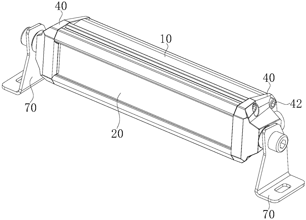
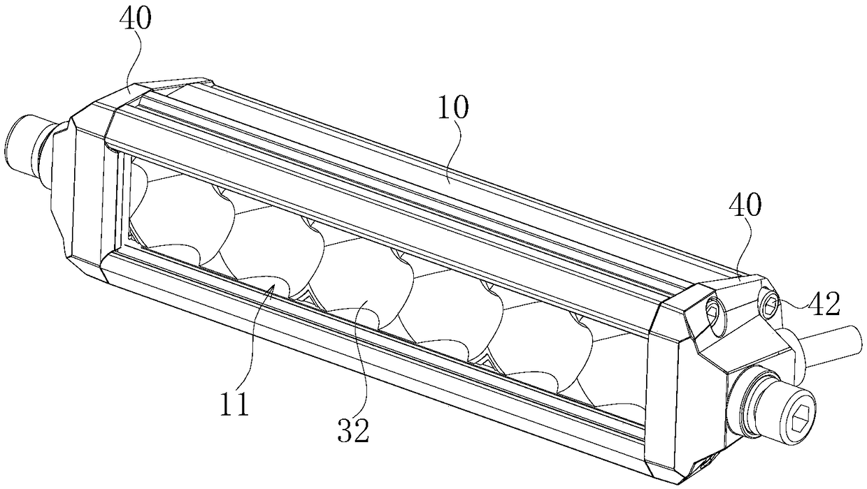
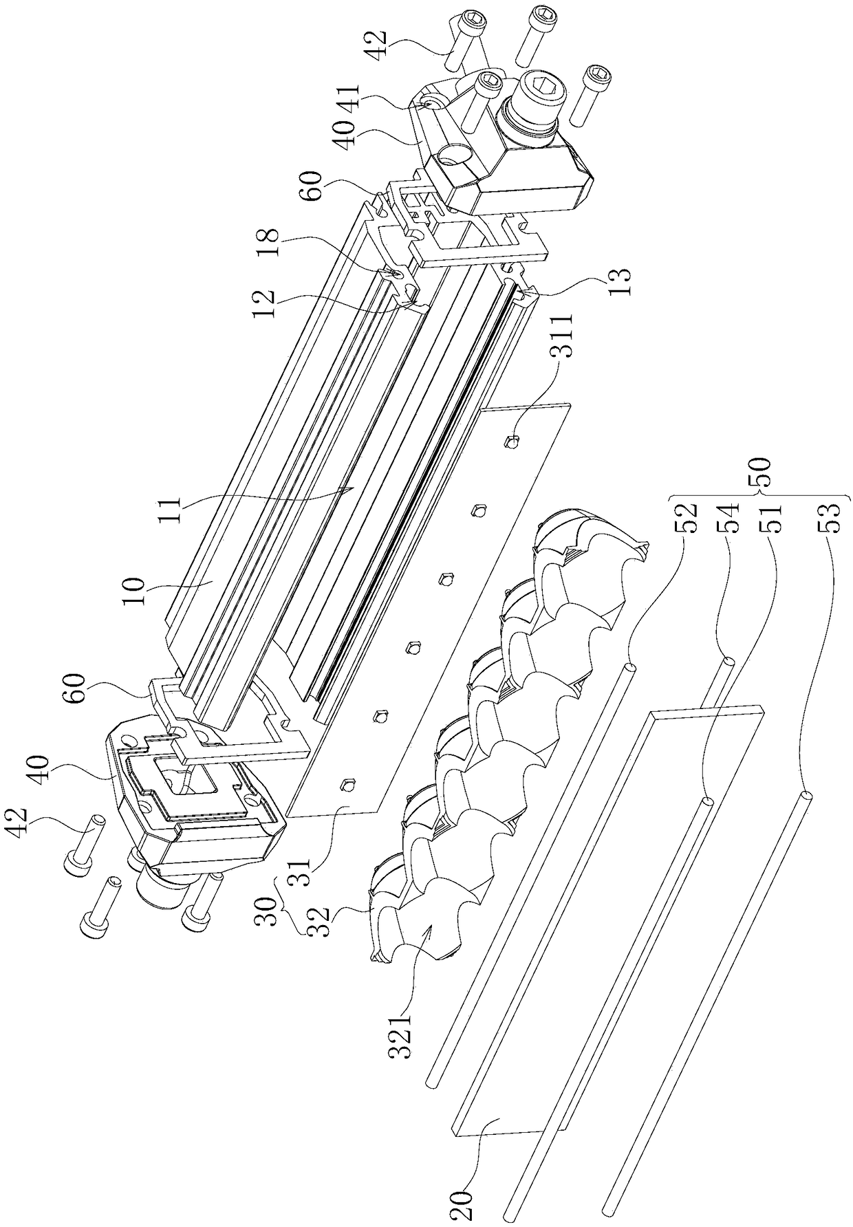
[0034] Embodiments of the present invention are described in detail below, examples of which are shown in the drawings, wherein the same or similar reference numerals designate the same or similar elements or elements having the same or similar functions throughout. Attached below by reference Figure 1~6 The described embodiments are exemplary and are intended to explain the present invention, but should not be construed as limiting the present invention.

[0035] In describing the present invention, it should be understood that the terms "length", "width", "upper", "lower", "front", "rear", "left", "right", "vertical", The orientation or positional relationship indicated by "horizontal", "top", "bottom", "inner", "outer", etc. are based on the orientation or positional relationship shown in the drawings, and are only for the convenience of describing the present invention and simplifying the description, rather than Nothing indicating or implying that a referenced device or...


PUM


Abstract

The invention belongs to the technical field of photo equipment, and particularly relates to a lamp. The lamp comprises a lamp housing, a light transmitting plate, a light source assembly, two end covers and a sealing strip assembly. The lamp housing is provided with a mounting cavity with the front side being provided with an opening. The light source assembly is arranged in the mounting cavity.An upper embedding groove and a lower embedding groove which correspond to each other up and down are formed in the position, close to the opening, of the inner wall of the mounting cavity. The upperend and the lower end of the light transmitting plate are embedded into the upper embedding groove and the lower embedding groove correspondingly and further abut against the inner wall of the upper embedding groove and the inner wall of the lower embedding groove through the sealing strip assembly. The two end covers are fixed to the two opposite ends of the lamp housing separately and further limit the light source assembly, the light transmitting plate and the sealing strip assembly from being disengaged from the two sides of the mounting cavity together. The gap between the light transmitting plate and the mounting cavity can be sealed and fixed in the butting mode by the sealing strip assembly. Therefore, the light transmitting plate can be fixed without fasteners, and the phenomenonthat the sealing property of the light transmitting plate can be influenced by water vapor in the long-term using process does not need to be worried.

Description

technical field [0001] The invention belongs to the technical field of photo equipment, and in particular relates to a lamp. Background technique [0002] At present, the existing photo equipment on the market, such as the light-transmitting panels on the front side of lamps such as car lights and spotlights, generally use traditional screw fastening methods to achieve fixed sealing and waterproofing. The aspect structure is relatively complex, resulting in large volume and high cost. On the other hand, the light-transmitting plate of the lamp is located at the front side and is easily exposed to water vapor, which causes the screws to rust easily, which in turn leads to a decrease in the stability of the subsequent fastening connection and poor sealing effect. Contents of the invention [0003] The object of the present invention is to provide a lamp, aiming to solve the technical problems in the prior art that the light-transmitting plate of the lamp is fastened by scre...

Claims


Application Information

Patent Timeline
Patent Type & Authority Applications(China)
IPC IPC(8): F21S8/00F21V3/00F21V15/01F21V15/015F21V17/16F21V29/74F21V31/00
CPCF21S8/00F21V3/00F21V15/01F21V15/015F21V17/16F21V29/74F21V31/005
Inventor 谢青波
Owner SHENZHEN AURORA TECH CO LTD
Why Eureka
Eureka Blog
Learn More