Shaft seal device of rotor pump

A shaft seal and rotor pump technology, applied to rotary piston/oscillating piston pump components, pump elements, machines/engines, etc., can solve the impact of shaft seal performance and shaft seal service life, and reduce the impact of fluid materials on machine seals The cooling effect of components, affecting the service life of the shaft seal of the rotor pump, etc., to improve the performance of the shaft seal, improve the service life, and prolong the service life

Active Publication Date: 2017-01-04
宁波邦威泵业有限公司
View PDF7 Cites 6 Cited by
  • Summary
  • Abstract
  • Description
  • Claims
  • Application Information

AI Technical Summary

Problems solved by technology

Due to the friction between the moving ring and the static ring when the rotor pump is working, the mechanical seals including the moving ring, the static ring and the O-ring are subject to heat and wear, resulting in a decline in performance. When there is obvious leakage of fluid materials, it needs to be shut down for maintenance.
Among the existing technical solutions, there is also a solution for lubricating the seal of the cooling machine by using the fluid material it transports. The mechanical seal is fixed in the axial direction. For example, the Chinese patent document CN201401323Y is a practical In the new public document, due to the high pressure of the fluid material entering and leaving the space where the machine seal is located, there is a greater extrusion force on the machine seal, and once too much accumulation does not circulate, it will continue to heat up, reducing the impact of the fluid material on the machine se

Method used


Image

  • Shaft seal device of rotor pump
  • Shaft seal device of rotor pump
  • Shaft seal device of rotor pump

Examples


Example Embodiment

[0031] Example 1

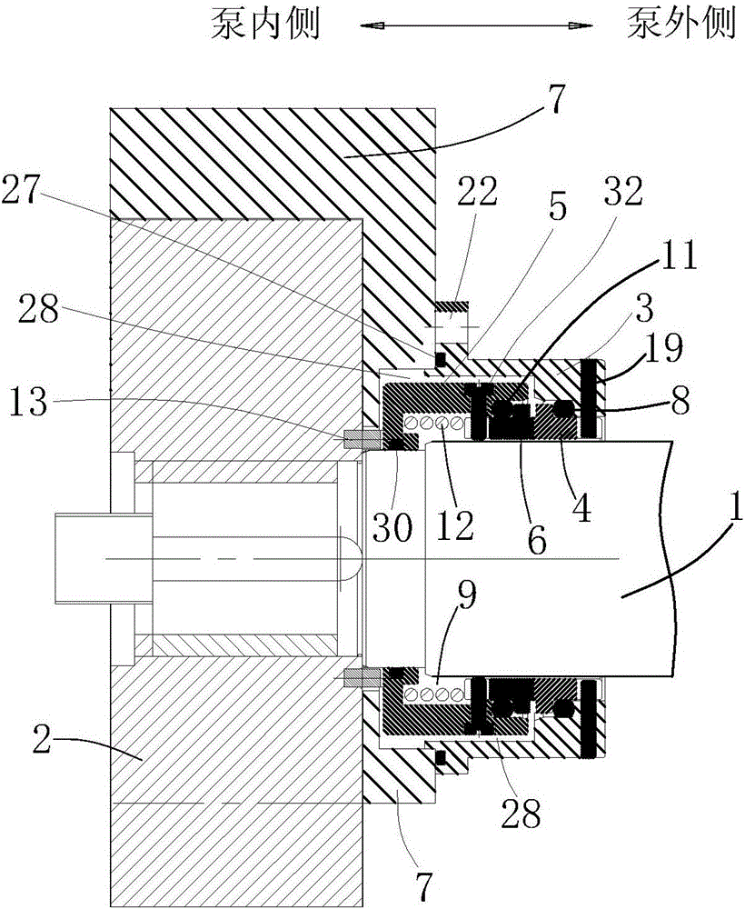
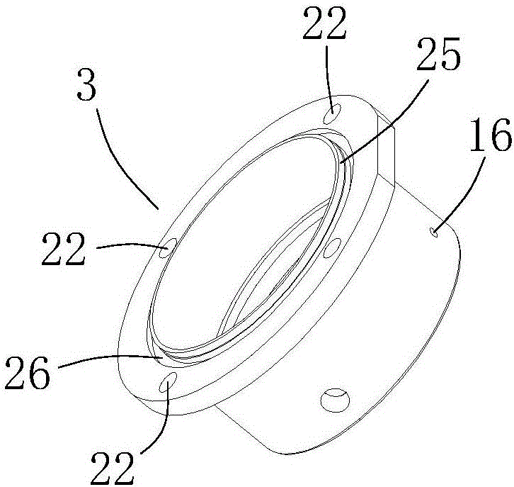
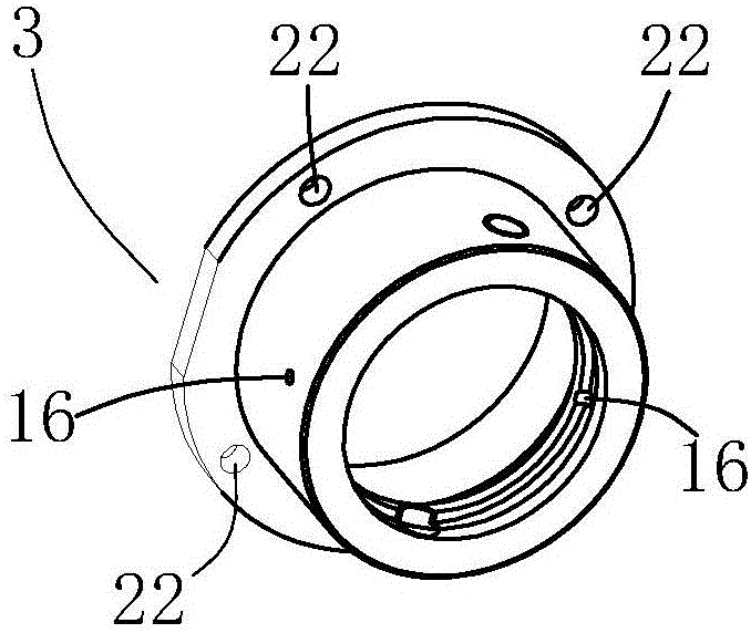
[0032] like figure 1 As shown, a shaft sealing device of a rotary lobe pump, the shaft 1 of the rotary lobe pump is fixedly connected with the impeller 2 as a rotor, and the shaft sealing device includes a mechanical seal seat 3 and a static ring 4, a movable ring seat 5 and a movable ring driven by it. 6. Both are cylindrical and sleeved on the outside of the shaft 1. The machine seal seat 3 is sleeved outside the moving ring seat 5 and is fixedly connected with the pump body 7. A cavity 28 is formed between the machine seal seat 3 and the moving ring seat 5. The inner side of the pump of the sealing seat 3 is the flange end connected to the pump body 7, and a plurality of connecting holes 22 are opened along the circumference of the flange end for fixed connection with the pump body 7; the outer side of the pump of the sealing seat 3 is closed with a smaller inner diameter. At the end, the static ring 4 is located in the inner cavity of the machine seal s...

Example Embodiment

[0043] Embodiment 2

[0044] like Figure 10 , Figure 11 As shown, on the basis of the first embodiment, a skeleton oil seal 20 is also arranged on the closed end of the mechanical seal seat 3 in this embodiment, and the others are completely the same as the embodiment. The inner ring of the skeleton oil seal 20 is in close contact with the shaft 1 of the rotor pump, and lubricating oil or cooling water is introduced into the sealed area to form an additional cooling and lubricating system. In this way, when there is no material in the pump, the dry grinding of the mechanical seal can be effectively prevented, and the service life of the rotor pump shaft seal can be further improved. In addition, a shaft sleeve can be added to the section where the skeleton oil seal 20 of the shaft 1 is located to prevent the shaft 1 from being rubbed by the lip of the skeleton oil seal 20 .


PUM


Abstract

Provided is a shaft seal device of a rotor pump. The shaft seal device comprises a mechanical seal base (3), a fixed ring (4), a moving ring base (5) and a moving ring (6) driven by the moving ring base (5). A first O-shaped ring (8) is arranged in a slit between the fixed ring (4) and the mechanical seal base (3). A tube body of the moving ring base (5) extends into the inner cavity of the mechanical seal base (3), an inner cavity (9) of the moving ring base, which is closed, is formed between the tube body of the moving ring base (5) and a shaft (1), a second O-shaped ring (11) is arranged in a slit between the moving ring (6) and the moving ring base (5). A compressive spring (12) is arranged between a connected end of the moving ring base (5) and the moving ring (6), and the moving ring (6) is in close contact with the fixed ring (4). A third O-shaped ring (30) is arranged between a connected end of the moving ring base (5) and the shaft (1). The moving ring base (5) is connected with an impeller (2) through at least one drive pin (13); one end of each drive pin (13) is in close-fit connection and the other end thereof is in floating insertion. By the shaft seal device of the rotor pump, performance of the rotor pump is improved and service life thereof is prolonged effectively. The shaft seal device is particularly applicable to shaft sealing of hygiene-grade rotor pumps.

Description

technical field [0001] The invention relates to a shaft sealing device of a rotor pump, in particular to a mechanical shaft sealing device of a sanitary rotor pump. Background technique [0002] Rotor pumps are also called colloid pumps, impeller pumps, universal delivery pumps, etc. Because their impellers are shaped like cams, they are also called cam pumps. Rotor pumps are positive displacement pumps; they are generally double rotors. The rotor pump achieves the purpose of conveying fluid materials by means of the periodic conversion of multiple fixed volume delivery units in the working chamber. Usually, a pair of synchronous gears are driven by a motor to drive the main and auxiliary shafts, and the double rotors are driven by the main and auxiliary shafts to rotate synchronously and in opposite directions, so that the volume of the pump changes, thereby forming a higher vacuum degree and discharge pressure; inlet It is a low-pressure area, and the outlet is a high-pre...

Claims


Application Information

Patent Timeline
IPC IPC(8): F04C15/00
CPCF04C15/0023F04C15/0088F04C15/0096
Inventor 谭在良
Owner 宁波邦威泵业有限公司
Why Eureka
Try Eureka