Magnetic coupling transmission system

A transmission system and magnetic coupling technology, applied in the direction of electrical components, circuit devices, battery circuit devices, etc., can solve the problems of reduced power efficiency of the receiving device, lower power efficiency of the receiving device, and increase the distance of wireless charging, etc., to achieve the goal of increasing the distance Effect

Inactive Publication Date: 2018-12-14
SHENZHEN TESILA WIRELESS EQUIP CO LTD
View PDF2 Cites 3 Cited by
  • Summary
  • Abstract
  • Description
  • Claims
  • Application Information

AI Technical Summary

Problems solved by technology

As a result, the power efficiency of the receiving device is reduced
[0004] Therefore, there is a need in the prior art for a technology capable of increasing the wireless charging distance without reducing the power efficiency of the receiving device

Method used


Image

  • Magnetic coupling transmission system
  • Magnetic coupling transmission system
  • Magnetic coupling transmission system

Examples


Embodiment Construction

[0032] In order to make the object, technical solution and advantages of the present invention clearer, the present invention will be further described in detail below in conjunction with the accompanying drawings and embodiments. It should be understood that the specific embodiments described here are only used to explain the present invention, not to limit the present invention. Based on the embodiments of the present invention, all other embodiments obtained by persons of ordinary skill in the art without making creative efforts belong to the protection scope of the present invention.

[0033] In addition, the technical solutions of the various embodiments can be combined with each other, but it must be based on the realization of those skilled in the art. When the combination of technical solutions is contradictory or cannot be realized, it should be considered that the combination of technical solutions does not exist , nor within the scope of protection required by the p...


PUM


Abstract

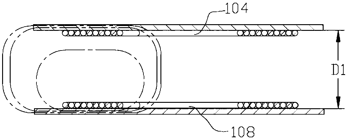
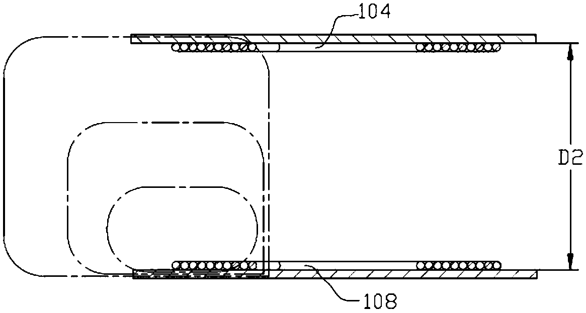
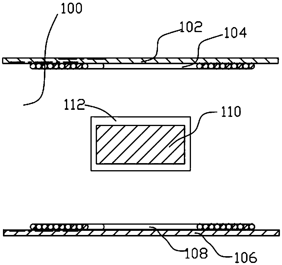
The invention provides a magnetic coupling transmission system, comprising a receiving coil arranged in a receiving device housing, a transmitting coil arranged in the transmitting device housing anda protective housing internally provided with a magnetic line of force aggregate, wherein the protective housing is located between the receiving device housing and the transmitting device housing; Amagnetic line of force aggregate is use to provide the path with the highest permeability between the transmit coil and the receive coil, so as to guide the magnetic lines of force generated by the transmitting coil to preferentially pass through the magnetic field line aggregate and then through the receiving coil, or to guide the magnetic lines of force generated by the transmitting coil moduleto preferentially pass through the receiving coil module and then through the magnetic field line aggregate module to return from the magnetic line of force aggregate module to the transmitting coil module. The invention can improve the density of magnetic lines of force passing through the receiving coil in the wireless charging process, so that when the distance between the receiving coil and the transmitting coil is long and the output power of the transmitting end is constant, the receiving power of the receiving end is not significantly reduced.

Description

technical field [0001] The invention relates to the field of wireless power transmission, in particular to a magnetic coupling transmission system capable of maintaining high power efficiency when the distance between the receiving coil module and the transmitting coil module is relatively long. Background technique [0002] With the development of wireless charging technology, wireless charging devices / receiving devices have been widely used in the energy supply of various mobile electric devices. At present, in commonly used wireless charging schemes, the magnetic coupling distance between the receiving coil module in the housing of the receiving device of a mobile phone and the transmitting coil module in the housing of the transmitting device cannot be too far, generally not exceeding 5 mm or the maximum distance of the transmitting coil module Outer dimension . Otherwise, when the output power of the transmitting device is constant, with the increase of the magnetic ...

Claims


Application Information

Patent Timeline
Patent Type & Authority Applications(China)
IPC IPC(8): H02J50/10H01F27/28
CPCH02J7/025H01F27/28H02J50/10
Inventor 邢益涛
Owner SHENZHEN TESILA WIRELESS EQUIP CO LTD
Why Eureka
Try Eureka