An OTDR performance evaluation device and a method

A technology for evaluating devices and performance, applied in the field of optical equipment inspection, can solve the problems of cumbersome reading, large volume and weight, unstable mechanical structure, etc., and achieve the effect of wide functional coverage

Active Publication Date: 2018-12-14
GUANGZHOU GRG METROLOGY & TEST CO LTD
View PDF30 Cites 4 Cited by
  • Summary
  • Abstract
  • Description
  • Claims
  • Application Information

AI Technical Summary

Problems solved by technology

However, this standard device has the disadvantages of large volume and weight, and unstable mechanical structure; other institutions have made some improvements to the standard device based on its principle, such as reducing a disc that provides loss values. Although this is to a certain extent The weight of the instrument is reduced, but in the actual test loss process, it is necessary to manually find a stable interval in the length section and then manually mark it. The reading is more cumbersome, and the result of this test method is easily questioned by customers.

Method used


Image

  • An OTDR performance evaluation device and a method
  • An OTDR performance evaluation device and a method
  • An OTDR performance evaluation device and a method

Examples


Embodiment 1

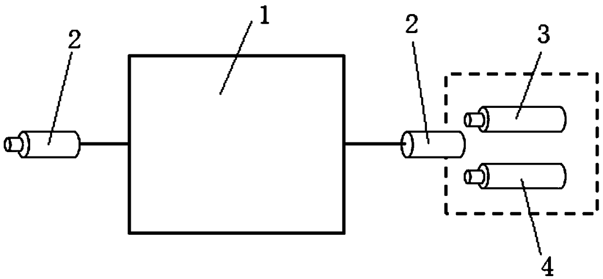
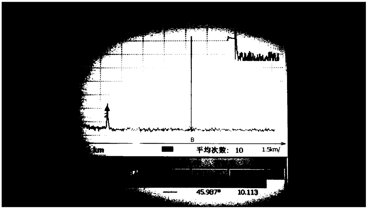
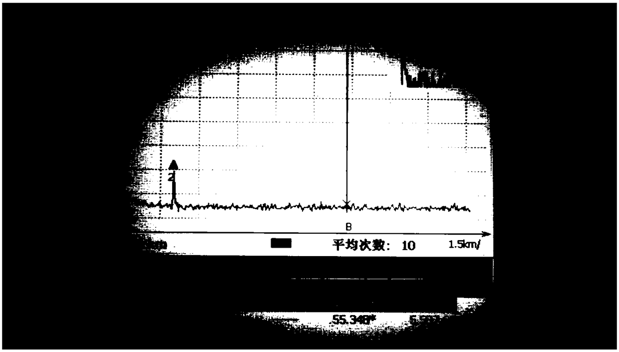
[0038] This embodiment is used to test the loss characteristics of the optical fiber. The two ends of the disc-type standard optical fiber 1 are FC / PC connectors, the insertion loss is ≤0.2, and the return loss is ≥50. One end of the standard optical fiber 1 is connected to the OTDR, and the other end is suspended in the air. , set the group refractive index of the OTDR to 1.4600, the pulse width to 100ns, and the average time to 10s, turn on the OTDR to emit optical pulse signals, change the parameters of the attenuator directly on the OTDR, and record the optical fiber in different states through the spectrum on the OTDR screen The loss characteristic display value of the segment, figure 2 and image 3 That is, the spectrum of this embodiment in different states with a length of 2.5km and a wavelength of 1310nm and a length of 2.5km and a wavelength of 1550nm can be directly read the fiber loss displayed in the upper left corner, and then compared with the loss parameter of...

Embodiment 2

[0040]This embodiment is used to test the length of the optical fiber. Both ends of the standard optical fiber 1 on the reel are FC / PC connectors, the insertion loss is ≤0.2, and the return loss is ≥50. One end of the coil-mounted standard optical fiber 1 is connected to the OTDR to be tested, and the other end is connected to the fiber optic mirror 3. Set the group refractive index of the OTDR to 1.4600, the pulse width to 100 ns, and the average time to 30 s; the optical fiber reflector 3 is a light reflection type device, and both the FRM type and the Sagnac ring type are acceptable. In this embodiment, the Sagnac ring type fiber with slightly weaker performance is selected The mirror cooperates with the standard optical fiber to simulate the length of the optical signal in multiple paths, and provides the corresponding magnitude. Use OTDR to emit light pulse signal, and then read the length value on the screen, compare it with the length of standard optical fiber 1 and its...

Embodiment 3

[0043] This embodiment is used to test the dynamic range, blind zone item test, and obtain the performance in terms of accuracy and noise control. When performing a dynamic range test, the vertical distance displayed by the OTDR at the corresponding set pulse width should be greater than the set signal strength. For example, when communication users require the OTDR to set the maximum pulse width, the dynamic range should be greater than 30dB . When performing a blind zone test, the lateral distance of the blind zone displayed by the OTDR should be less than the set distance under the corresponding set pulse width. For example, when communication users require the OTDR to set the minimum pulse width, the event blind zone should be less than 3m. Attenuation dead zone should be less than 5m. Use the parameters related to the measurement range and minimum resolution of the OTDR to judge whether the indication meets the requirements.

[0044] In this embodiment, both ends of the...


PUM

PropertyMeasurementUnit
Pulse widthaaaaaaaaaa

Abstract

The OTDR performance evaluation device of the invention comprises an OTDR and a disk-mounted standard optical fiber, wherein the standard optical fiber has an optical fiber connector, and the OTDR andthe standard optical fiber are connected through an optical fiber connector of the standard optical fiber. The OTDR performance evaluation method of the invention utilizes the OTDR and the standard optical fiber to test the optical fiber loss characteristics. The OTDR is connected with an optical fiber connector at one end of a standard optical fiber, and the optical fiber connector at the otherend of the standard optical fiber is connected with an optical fiber transmitting mirror, and the optical fiber length is tested. The OTDR is connected to the optical fiber connector at one end of thestandard optical fiber, and the optical fiber connector at the other end of the standard optical fiber is connected to the optical fiber trap for testing the dynamic range and blind area. The OTDR performance evaluation device and method of the invention can realize the functions of testing the length, loss, etc. of the OTDR, and the functions of testing the dynamic range, blind area and the like, so that the whole device is smaller and lighter without affecting the testing accuracy, and the function coverage is wider. The OTDR performance evaluation device and the OTDR performance evaluationmethod of the invention can realize the functions of testing the dynamic range, blind area and the like.

Description

technical field [0001] The invention belongs to the technical field of optical equipment detection, and in particular relates to an OTDR performance evaluation device, and also relates to a method for evaluating OTDR performance by using the device. Background technique [0002] The Optical Time Domain Reflectometer (OTDR) is made according to the principle of backscattering and Fresnel reflection of light, and uses the backscattering light generated when light propagates in the optical fiber to obtain attenuation information. The analysis of the measurement curve is an instrument for understanding the uniformity, defects, breakage, joint coupling and other properties of the optical fiber. This instrument can usually be used to measure parameters such as fiber length, elongation attenuation, joint loss, and fiber fault location. It is an indispensable tool in optical cable construction and monitoring, and plays an irreplaceable role in the process of optical network construc...

Claims


Application Information

Patent Timeline
IPC IPC(8): H04B10/071
CPCH04B10/071
Inventor 王卓念张辉李文兴张国茂李建征龙阳
Owner GUANGZHOU GRG METROLOGY & TEST CO LTD
Why Eureka
Try Eureka