A non-contact non-destructive testing method and device for thermal barrier coating insulation temperature

A technology for thermal barrier coatings and non-destructive testing, which is applied in the directions of measuring devices, radiation pyrometry, and thermal development of materials, etc. It can solve problems such as difficulty in characterizing the thermal insulation effect of coatings, uncertainty, and test data delays. The effect of wide application range, simple operation and simple device structure

Active Publication Date: 2021-12-28
XI AN JIAOTONG UNIV
View PDF8 Cites 0 Cited by
  • Summary
  • Abstract
  • Description
  • Claims
  • Application Information

AI Technical Summary

Problems solved by technology

In terms of coating surface heating means, radiation heating in the furnace is used, which is different from the heat transfer mode of the actual hot plate gas convection, supplemented by high-temperature radiation; in terms of testing means, the heat conduction of the armored shell has a certain delay, and the thermocouple itself It will affect the airflow field and temperature field on the surface of the coating and the substrate side, resulting in delay and uncertainty in the test data;
In terms of the test environment, it is difficult to change the gas characteristics, the interaction between coating insulation and gas film holes cannot be considered, and the actual blade service conditions such as calcium magnesium silicon oxide particles cannot be added, which are quite different from the blade service state, and it is difficult to characterize the coating insulation. heat effect
In terms of test content, only short-term heat insulation performance can be measured, without considering the influence of service time, environment, and coating thickness on heat insulation effect; in terms of applicability, it is difficult to meet the measurement of heat insulation effect distribution on the entire surface of blades with complex profiles
The above factors make it very difficult to evaluate the thermal insulation effect of coatings under different working conditions in the design of turbine air-cooled blades. This engineering problem needs to be solved urgently

Method used


Image

  • A non-contact non-destructive testing method and device for thermal barrier coating insulation temperature
  • A non-contact non-destructive testing method and device for thermal barrier coating insulation temperature

Examples


Embodiment 1

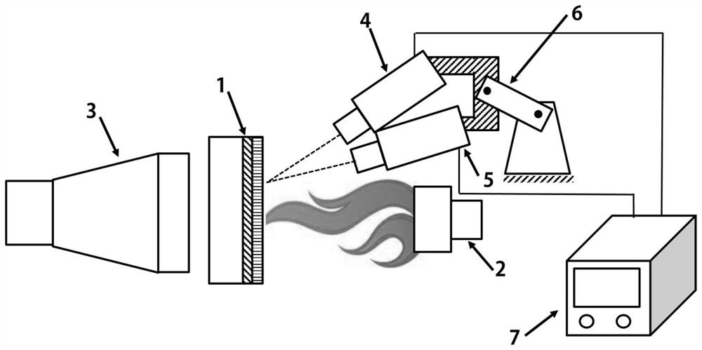
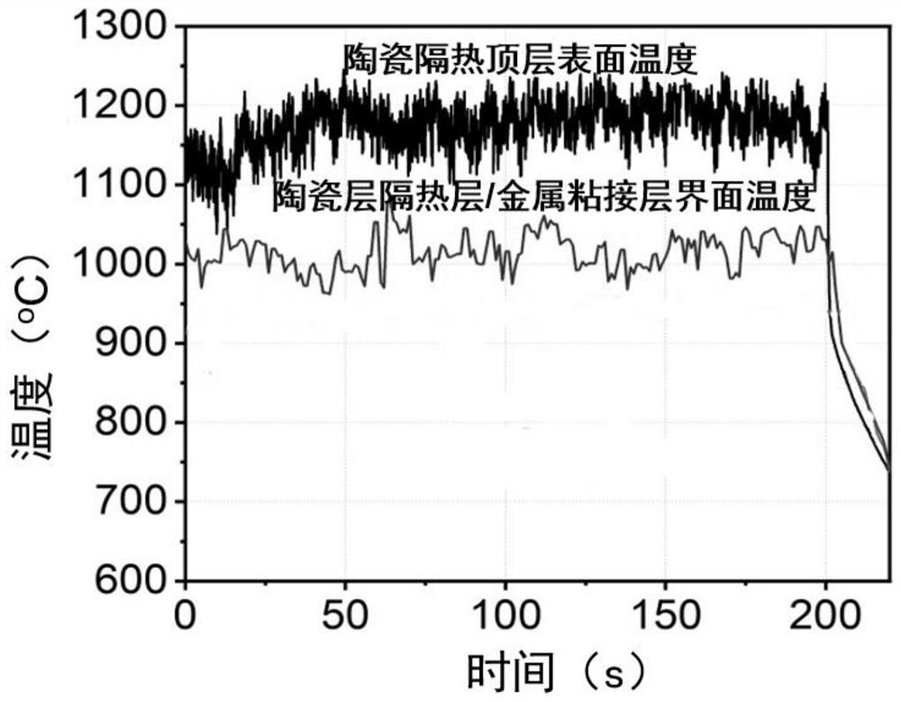
[0047] Such as figure 1 As shown, the DD6 nickel-based single crystal superalloy with a diameter of 25.4 mm and a thickness of 2.5 mm was used as the substrate, and a NiCoCrAlY metal bonding layer with a thickness of 120 μm was prepared on the surface of the superalloy substrate by low-pressure plasma spraying technology. Technology Prepare an 8YSZ ceramic thermal insulation top layer with a thickness of 250 μm on the surface of the metal bonding layer, and use the above-mentioned superalloy sheet with a thermal barrier coating as the thermal barrier coating sample 1 of the superalloy substrate to be tested.

[0048] The oxyacetylene flame gun is used as the surface heating device 2 of the thermal barrier coating ceramic heat insulation top layer, and the oxyacetylene flame is used to heat the surface of the thermal barrier coating ceramic heat insulation layer to simulate the effect of high temperature gas on the blade surface thermal barrier coating in the actual service envi...

Embodiment 2

[0051] Firstly, using the equiaxed nickel-based superalloy with a diameter of 25.4 mm and a thickness of 2.5 mm as the substrate, a NiCoCrAlY metal bonding layer with a thickness of 120 μm was prepared on the surface of the superalloy substrate by low-pressure plasma spraying technology, and an electron beam physical vapor phase The 8YSZ ceramic thermal insulation top layer with a thickness of 200 μm was prepared on the surface of the metal bonding layer by deposition method, and the above-mentioned superalloy sheet with thermal barrier coating was used as the superalloy component with thermal barrier coating.

[0052] Use an oxyacetylene flame gun as the surface heating device 2 of the ceramic heat insulation top layer of the thermal barrier coating, use a compressed air gun to cool the surface of the superalloy substrate with a thermal barrier coating, and obtain a theoretical heat insulation temperature of 200°C by adjusting the cooling air flow rate. conditions for experime...

Embodiment 3

[0055] Firstly, using the directionally solidified nickel-based superalloy with a diameter of 25.4 mm and a thickness of 2.5 mm as the substrate, a NiCoCrAlY metal bonding layer with a thickness of 150 μm was prepared on the surface of the superalloy substrate by low-pressure plasma spraying technology. 8YSZ ceramic thermal insulation top layer with a thickness of 500 μm was prepared on the surface of the metal bonding layer, and the above-mentioned superalloy sheet with thermal barrier coating was used as a superalloy component with thermal barrier coating.

[0056] The oxyacetylene flame gun is used as the surface heating device of the thermal barrier coating ceramic heat insulation top layer, and the oxyacetylene flame is used to heat the surface of the thermal barrier coating ceramic heat insulation layer to simulate the effect of high temperature gas on the blade surface thermal barrier coating in the actual service environment. Thermal shock: using a compressed air gun as...


PUM

PropertyMeasurementUnit
wavelengthaaaaaaaaaa
diameteraaaaaaaaaa
thicknessaaaaaaaaaa

Abstract

The invention discloses a non-contact non-destructive testing method and device for thermal barrier coating insulation temperature, which belongs to the technical field of non-destructive testing. Firstly, the real service environment is simulated, the surface of the thermal barrier coating ceramic layer is heated, and the superalloy substrate is heated. The surface is cooled, and the temperature at the interface between the ceramic top layer and the back of the ceramic layer and the metal bonding layer of the superalloy component with thermal barrier coating is measured by an infrared thermometer. Compared with the existing thermocouple contact temperature test technology, the method of the present invention has non-contact measurement, does not affect the surface of the thermal barrier coating and the original gas flow field and temperature field inside the air channel of the hollow blade, has fast response to temperature test, and simple test process The advantage of this method is that it is more practical.

Description

technical field [0001] The invention belongs to the technical field of non-destructive testing, and relates to an infrared temperature testing method, in particular to a non-contact non-destructive testing method and device for the heat insulation temperature of a thermal barrier coating. Background technique [0002] Thermal barrier coatings (TBCs: Thermal Barrier Coatings) are widely used in aero-engine and gas turbine superalloy hot-end parts for high-temperature heat insulation protection for superalloy parts, and can significantly improve the conversion efficiency of aero-engines and gas turbines. The thermal barrier coating is composed of a metal bonding layer and a ceramic heat-insulating top layer. The main component of the metal bonding layer is MCrAlY (M=Ni, Co) or NiAlPt, which mainly plays a role in resisting high-temperature oxidation and relieving the ceramic heat-insulating top layer and high-temperature alloy. The effect of mismatching thermophysical properti...

Claims


Application Information

Patent Timeline
Patent Type & Authority Patents(China)
IPC IPC(8): G01N25/20G01J5/00
CPCG01N25/20G01J5/00G01J2005/0077
Inventor 李长久雒晓涛杨冠军
Owner XI AN JIAOTONG UNIV
Why Eureka
Try Eureka