
Fracture external fixing rack installation assembly

A technology for installing components and fixing frames, which is applied in the field of fracture locating frames, and achieves the effects of simple structure, good recovery and simplified operation workload.

Active Publication Date: 2018-12-18
陈聚伍
View PDF7 Cites 6 Cited by
  • Summary
  • Abstract
  • Description
  • Claims
  • Application Information

AI Technical Summary

Problems solved by technology

[0003] The present invention aims at various disadvantages of current fracture fixation methods, and provides a fracture external fixation mounting assembly with simplified structure but better practicability, so as to achieve the purpose of minimally invasive and simplified structure, which is beneficial to the flexible movement of patients during the recovery period, and reduce medical costs

Method used


Image

  • Fracture external fixing rack installation assembly
  • Fracture external fixing rack installation assembly
  • Fracture external fixing rack installation assembly

Examples


Embodiment 1

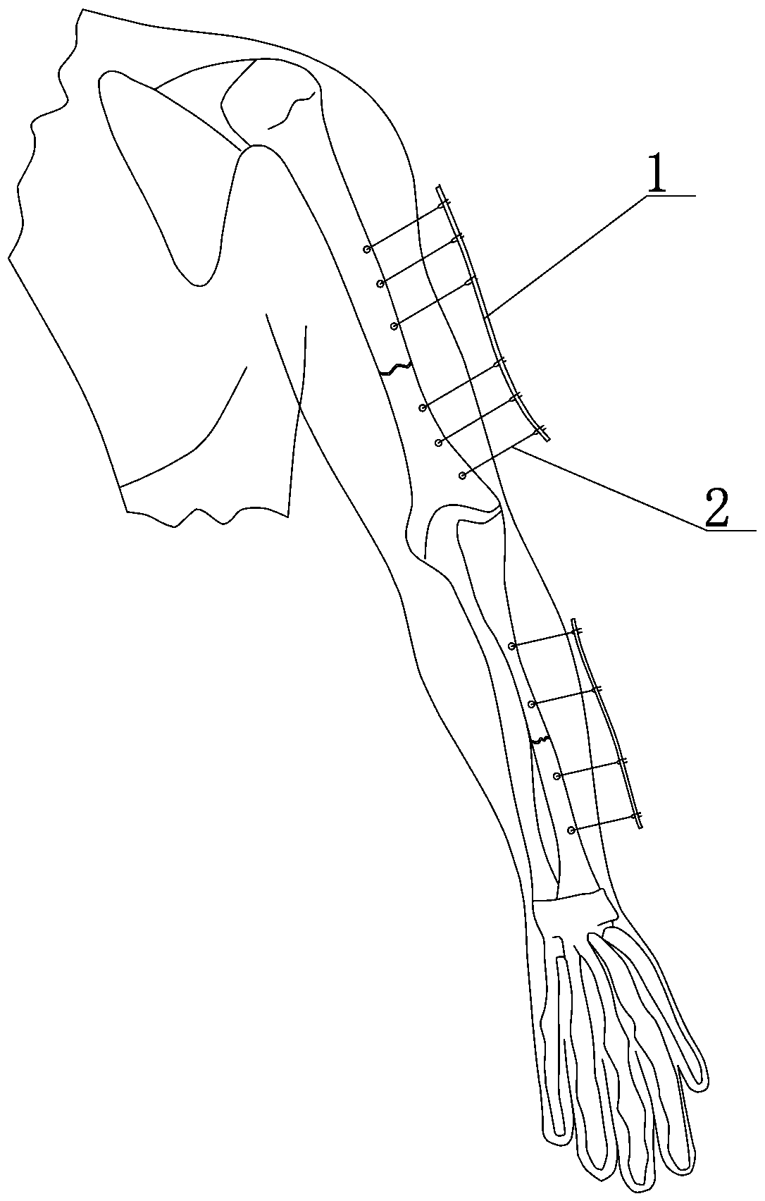
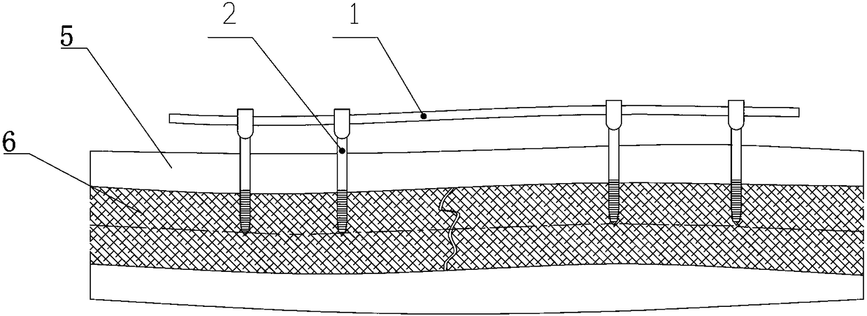
[0025] Embodiment 1: as figure 1 and figure 2 The shown fracture external fixator installation assembly includes an anatomical rod 1 and a plurality of Y-shaped radial fixation nails 2 . Among them, each Y-shaped radial fixation nail 2 is vertically fixed on the bone layer 6 on both sides of the fracture site, and the anatomical rod 1 is an arc-shaped rod consistent with the curvature of the fracture site, and the anatomical rod 1 is fixed on each Y-shaped radial fixation The end of nail 2 constitutes a fixed whole. Since the curvature of the anatomical rod 1 is consistent with the fracture site, the anatomical rod 1 and the fracture site can be kept in an approximately parallel state, so that the anatomical rod 1 can be used to connect and strengthen the two sides of the fracture to ensure a stable butt joint of the fracture site.

[0026] Such as image 3 As shown, the upper end of each Y-shaped radial fixing nail 2 is provided with a Y-shaped fork 21 , the middle part i...

Embodiment 2

[0036] Embodiment 2: On the basis of Embodiment 1, another positioning sleeve 4 is adopted, such as Figure 12 shown. The inner wall of the horizontal tube 41 of the positioning sleeve 4 is a cylindrical hole 47 , and an inner sleeve 44 is set in the cylindrical hole 47 , and a locking screw 46 is connected between the horizontal tube 41 and the inner sleeve 44 . The inner wall of the inner sleeve 44 is provided with an anti-rotation block 45 parallel to the axial direction. This is a positioning sleeve 4 with a composite structure, in which the inner sleeve 44 and the model positioning rod cannot rotate, which ensures the anti-rotation constraint relationship. The horizontal tube 41 can rotate along the inner sleeve 44, but it can be locked by the locking screw 46 to ensure that the horizontal tube 41 and the inner sleeve 44 do not rotate. This embodiment can realize the purpose of the rotation of the horizontal tube 41 and the inner sleeve 44 under special circumstances, i...

Embodiment 3

[0037] Embodiment 3: on the basis of embodiment 1, adopt such as Figure 13 As shown in the fixed sleeve, the inner wall of the horizontal tube 41 of the positioning sleeve 4 is a cylindrical hole 47, and the horizontal tube 41 is matched with the end of each model positioning rod. Horizontal tube 41 side walls are vertically provided with locking screw 46, utilize locking screw 46 to fix together horizontal tube 41 and each model positioning bar end.


PUM


Abstract

The invention discloses a fracture external fixing rack installation assembly. The fracture external fixing rack installation assembly comprises a dissection rod, a group of model positioning rods, apositioning sleeve, and a plurality of Y-shaped radial fixing nails vertically fixed to a bone layer at two sides of a fracture position, the upper end of each Y-shaped radial fixing nail is providedwith a Y-shaped fork head, the middle portion is provided with a polished rod section, the lower end is provided with a screw rod section, the center of the Y-shaped fork head is provided with a locking pin, the bottom of the locking pin is supported at the upper side of the dissection rod, and the positioning sleeve comprises a transverse pipe and a vertical guide pipe vertically connected with the end of the transverse pipe. According to the fracture external fixing rack installation assembly, the structure is simple, trauma to a patient caused by an operation can be reduced as much as possible, the size and the weight of an external support during the rehabilitation stage of the patient can be reduced, the action flexibility of the patient in the rehabilitation stage is improved, the compression on the fracture position by the external support is reduced, and the recovery is facilitated.

Description

Technical field: [0001] The invention belongs to the technical field of fracture positioning frames, and in particular relates to an installation component of an external fracture positioning frame. Background technique: [0002] Outer frame fixation is a commonly used fracture fixation method. The existing outer frame fixation usually uses fixing nails vertically driven into both sides of the fracture, and then connects multiple universal joints and connecting rods to form a fixed frame. Since the universal joints require The adjustment relationship between horizontal rotation and locking and vertical rotation and locking, the universal wheel is relatively large, and the entire outer frame is relatively large. It is inconvenient for patients with fractures to carry after installation and use. The fracture site cannot wear and change clothes, which affects foreign-related activities. To develop a fracture fixation outer frame that is easy to operate, convenient to carry and ...

Claims


Application Information

Patent Timeline
Patent Type & Authority Applications(China)
IPC IPC(8): A61B17/64
CPCA61B17/64
Inventor 陈聚伍
Owner 陈聚伍
Learn More