Ultrasonic cleaning machine used for production of LED lamp

The technology of an ultrasonic cleaning machine and LED lights is applied in the direction of cleaning methods using liquids, cleaning methods and utensils, chemical instruments and methods, etc., which can solve the problems of large footprint, complex structure, and prone to mechanical failures, and achieve structural Simple, not easy to mechanical failure, small footprint effect

Inactive Publication Date: 2018-12-18
TIANJIN TIANXING ELECTRONICS
View PDF0 Cites 0 Cited by
  • Summary
  • Abstract
  • Description
  • Claims
  • Application Information

AI Technical Summary

Problems solved by technology

[0002] LED lamp is a new type of lighting fixture. When manufacturing LED lamps, there is a lot of dust on the surface and inside of the lamp, which will seriously affect the photometric effect of LED lamps. Ultrasonic cleaning machines for LED lamp production can completely remove stains Stay away from the lamp, so that the LED lamps produced in this way are more uniform and soft, without black holes and yellow circles. However, most of the existing LED lamp ultrasonic cleaning machines use a straight-line structure with multiple working tanks placed side by side. This structure occupies an area of Large, complex structure, and the transfer of LED lights between multiple working slots needs to be driven by a conveyor belt or a traversing structure, which is prone to mechanical failures

Method used


Image

  • Ultrasonic cleaning machine used for production of LED lamp
  • Ultrasonic cleaning machine used for production of LED lamp
  • Ultrasonic cleaning machine used for production of LED lamp

Examples


Embodiment Construction

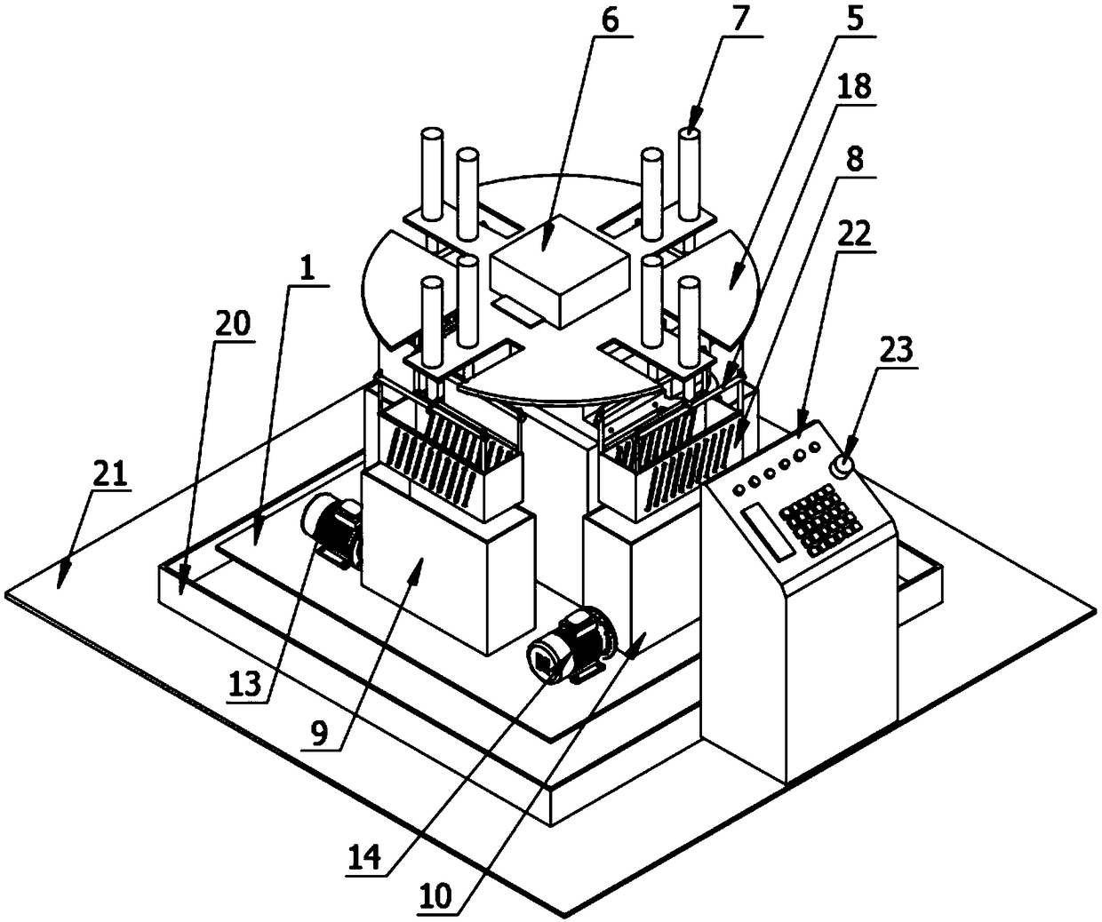
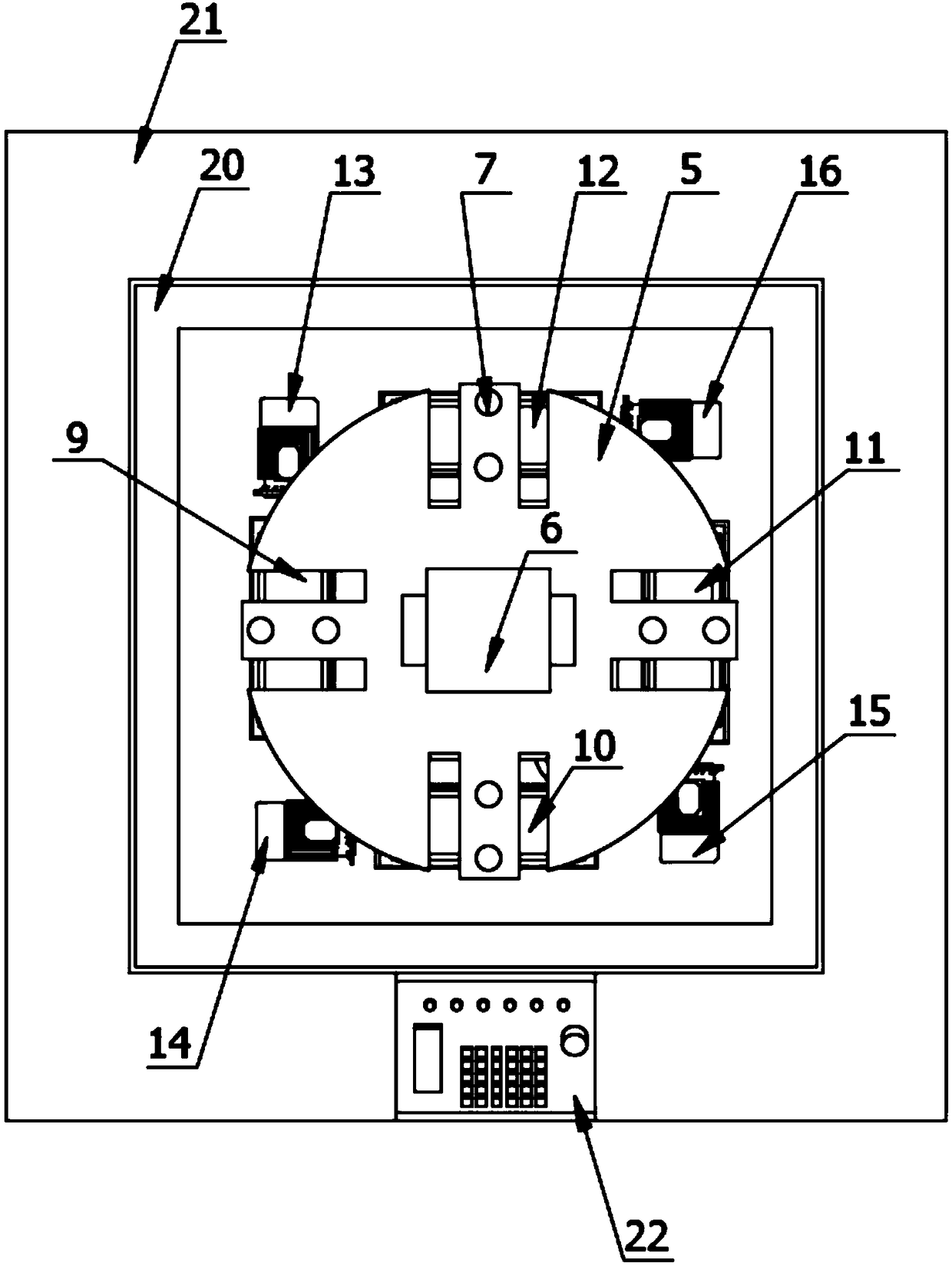
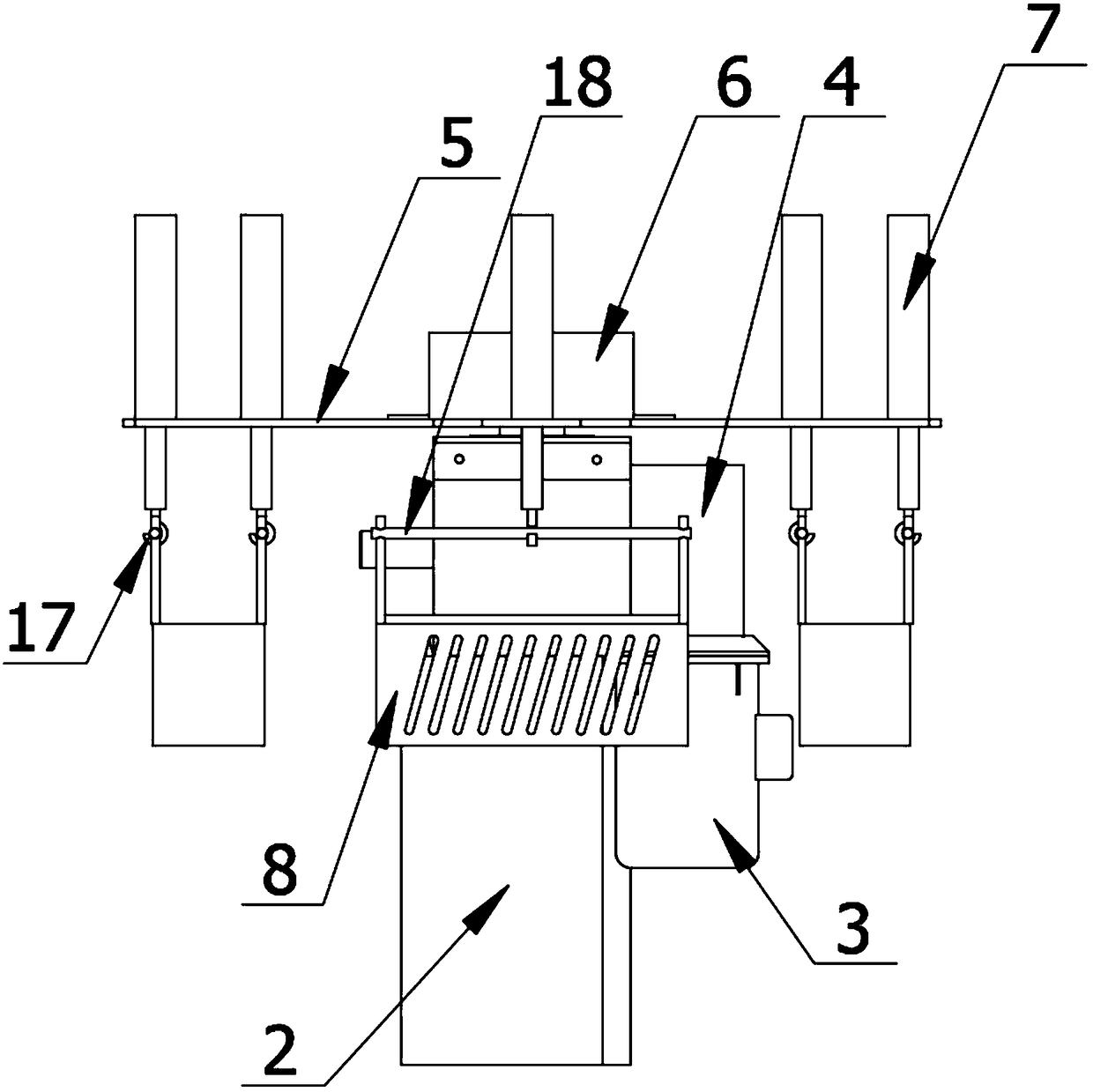
[0019] The present invention is specifically described below in conjunction with accompanying drawing, as Figure 1-5 As shown, an ultrasonic cleaning machine for LED lamp production includes a rotary lifting device, a cleaning device, a base 1 and a control circuit. The servo motor 3 on the motor base 2, the reducer 4 connected to the main shaft of the servo motor 3, the index turntable 5 arranged on the output shaft of the reducer 4, and the index turntable 5 arranged at the center of the index turntable 5 Cable box 6, the indexing turntable 5 is a common carrying tool for mechanical processing, and a special indexing turntable 5 can be customized according to actual needs. The indexing turntable 5 described in this device is provided with four synchronous electric push rods 7 installation positions, for the installation of the synchronous electric push rod 7, the power supply mode that the reducer 4 is connected with the servo motor 3 is used to control the rotation and sto...


PUM


Abstract

The invention provides an ultrasonic cleaning machine used for production of an LED lamp. The ultrasonic cleaning machine used for production of the LED lamp comprises a rotary lifting device, a cleaning device, a base and a control circuit. The rotary lifting device is composed of a motor base arranged on the base, a servo motor arranged on the motor base, a speed reducer connected with a spindleof the servo motor, an indexing turntable arranged on an output shaft of the speed reducer and a cable box arranged at the center of the indexing turntable. The structure that a synchronous electricpush rod is mounted on the indexing turntable to pull an LED lamp frame is adopted, so that common parallel working troughs are replaced by circularly-distributed working troughs; the indexing turntable is driven by the servo motor and the speed reducer jointly, so that the clear water spraying procedure, the ultrasonic cleaning procedure, the draining procedure and the air-drying procedure are conducted more accurately; the occupied area is small, and the structure is simple; and the LED lamp is driven by the indexing turntable to be transferred between the working troughs in the circumferential direction, so that a conveying belt or a horizontal moving mechanism is not needed anymore, and thus, mechanical faults are unlikely to happen.

Description

technical field [0001] The invention relates to the field of ultrasonic cleaners, in particular to an ultrasonic cleaner for LED lamp production. Background technique [0002] LED lamp is a new type of lighting fixture. When manufacturing LED lamps, there is a lot of dust on the surface and inside of the lamp, which will seriously affect the photometric effect of LED lamps. Ultrasonic cleaning machines for LED lamp production can completely remove stains Stay away from the lamp, so that the LED lamps produced in this way are more uniform and soft, without black holes and yellow circles. However, most of the existing LED lamp ultrasonic cleaning machines use a straight-line structure with multiple working tanks placed side by side. This structure occupies an area of Large, complex structure, and the transfer of LED lights between multiple working slots needs to be driven by a conveyor belt or a traversing structure, which is prone to mechanical failure. Contents of the inve...

Claims


Application Information

Patent Timeline
Patent Type & Authority Applications(China)
IPC IPC(8): B08B3/02B08B3/12
CPCB08B3/02B08B3/12
Inventor 李晓辉曹锡文王红石海莲王蔚
Owner TIANJIN TIANXING ELECTRONICS
Why Eureka
Try Eureka