Cable cutting machine

A wire cutting machine and frame technology, applied in the field of wire cutting machines, can solve the problems of affecting cutting quality, time-consuming and labor-intensive, and poor control of length, etc.

Pending Publication Date: 2018-12-18
CHENGWU POWER SUPPLY CO STATE GRID SHANDONG ELECTRIC POWER CO LTD
View PDF0 Cites 5 Cited by
  • Summary
  • Abstract
  • Description
  • Claims
  • Application Information

AI Technical Summary

Problems solved by technology

[0002] In the process of electric power construction, it is necessary to use many cables of the same length. The cables are very thick. If they are cut manually, it will be time-consuming and labor-intensive. One, and the efficiency is extremely low, so the applicant applied for an intelligent thread cutting machine on March 29, 2017, the application number is 2017101953431, which basically solved the above problems, but in use, we found that the above intelligent thread cutting machine There is also the following problem: when the conveying motor receives the stop signal and stops running, because there is a certain inertia, the conveying motor will rotate a little, and the driving wheel will also rotate a little at the same time, so that the cable is conveyed forward, so that while conveying While cutting, the conveying process is affected by the cutting and cannot be conveyed forward, which will cause the cable to arch forward and affect the cutting quality; in addition, in the process of forward conveying after cutting, the head end needs to be sent into the cable limiter

Method used


Image

  • Cable cutting machine
  • Cable cutting machine
  • Cable cutting machine

Examples


Embodiment Construction

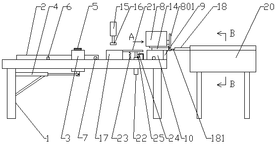
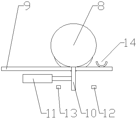
[0023] Accompanying drawing is the specific embodiment of the present invention. Such as Figure 1 to Figure 6 As shown, this thread cutting machine includes a frame 1 and a PLC control system, and the PLC control system controls the operation of the entire device. On the frame 1, a conveying system, a cutting system and a discharging system are installed in sequence, wherein:

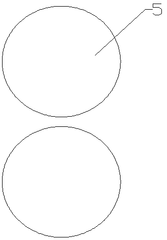
[0024] The conveying system includes: a slide rail 2 is installed on the frame 1, and there is a slide block 3 on the slide rail 2. The slide block 3 is fixed on the output end of the conveying cylinder 4, and the conveying cylinder 4 is installed under the slide rail 2. There are two ratchets 5 placed flat on the sliding block 3, and the two ratchets 5 are arranged front and back, that is to say, the line connecting the centers of the two ratchets 5 is perpendicular to the slide rail 2, and the rotation directions of the two ratchets 5 are opposite. The circumferential direction of 5 is inwardly rece...


PUM


Abstract

The invention relates to the field of power supply facilities, and particularly discloses a cable cutting machine. The cable cutting machine comprises a rack and a PLC control system. A conveying system, a cutting system and a discharging system are arranged on the rack. The conveying system comprises a conveying cylinder. A sliding block is arranged at the output end of the conveying cylinder. Two ratchet wheels are arranged on the sliding block. The sliding block is located on a sliding rail. Two travel switches are mounted on the sliding rail. A conveying trough is located in front of the sliding rail. A pressing cylinder is arranged between the sliding rail and the conveying trough and is provided with a pressing plate. The discharging system comprises a discharging pipe and a discharging hopper. According to the cable cutting machine, the two ratchet wheels are arranged and can rotate in only one direction, so that when an output shaft of the conveying cylinder is output, the tworatchet wheels are used as clamps to drive a cable to advance; and when the output shaft is retreated, the ratchet wheels rotate while the cable does not move under the combined action of the pressingcylinder, and the cylinder can stop instantly, so that the advancing inertia of the cable is prevented, and the defect that the cable is arched forwards when a motor is used is overcome.

Description

technical field [0001] The invention relates to the field of power supply facilities, in particular to a wire cutting machine. Background technique [0002] In the process of electric power construction, it is necessary to use many cables of the same length. The cables are very thick. If they are cut manually, it will be time-consuming and labor-intensive. One, and the efficiency is extremely low, so the applicant applied for an intelligent thread cutting machine on March 29, 2017, the application number is 2017101953431, which basically solved the above problems, but in use, we found that the above intelligent thread cutting machine There is also the following problem: when the conveying motor receives the stop signal and stops running, because there is a certain inertia, the conveying motor will rotate a little, and the driving wheel will also rotate a little at the same time, so that the cable is conveyed forward, so that while conveying While cutting, the conveying proc...

Claims


Application Information

Patent Timeline
Patent Type & Authority Applications(China)
IPC IPC(8): B21F11/00B21F23/00
CPCB21F11/00B21F23/00
Inventor 时圣雨王若冰邓雪梅李博岳海珍徐龙涛徐显洲商子英王伟纪二云张新
Owner CHENGWU POWER SUPPLY CO STATE GRID SHANDONG ELECTRIC POWER CO LTD
Why Eureka
Try Eureka