A cutting device for civil engineering components

A cutting device and civil engineering technology, applied in positioning devices, metal processing machinery parts, manufacturing tools, etc., can solve the problems of large labor consumption, poor cutting effect, low efficiency, etc., to reduce labor intensity, improve accuracy and stability Sex-enhancing effects

Active Publication Date: 2020-03-17
JIANGXI UNIV OF SCI & TECH
View PDF5 Cites 0 Cited by
  • Summary
  • Abstract
  • Description
  • Claims
  • Application Information

AI Technical Summary

Problems solved by technology

[0004] In view of the above-mentioned shortcomings of the prior art, the purpose of the present invention is to provide a cutting device for civil engineering components, which is used to solve the problems of low efficiency, labor-intensive and poor cutting effect of angle steel cutting in existing civil engineering components

Method used


Image

  • A cutting device for civil engineering components
  • A cutting device for civil engineering components
  • A cutting device for civil engineering components

Examples


Embodiment 1

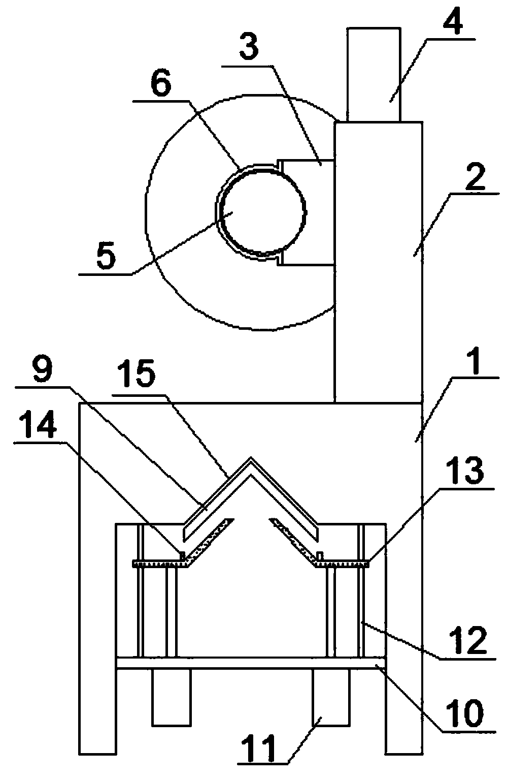
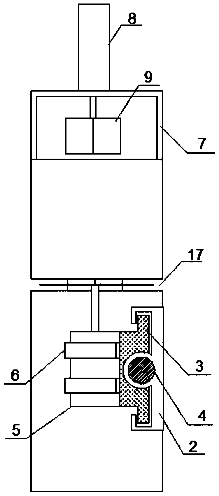
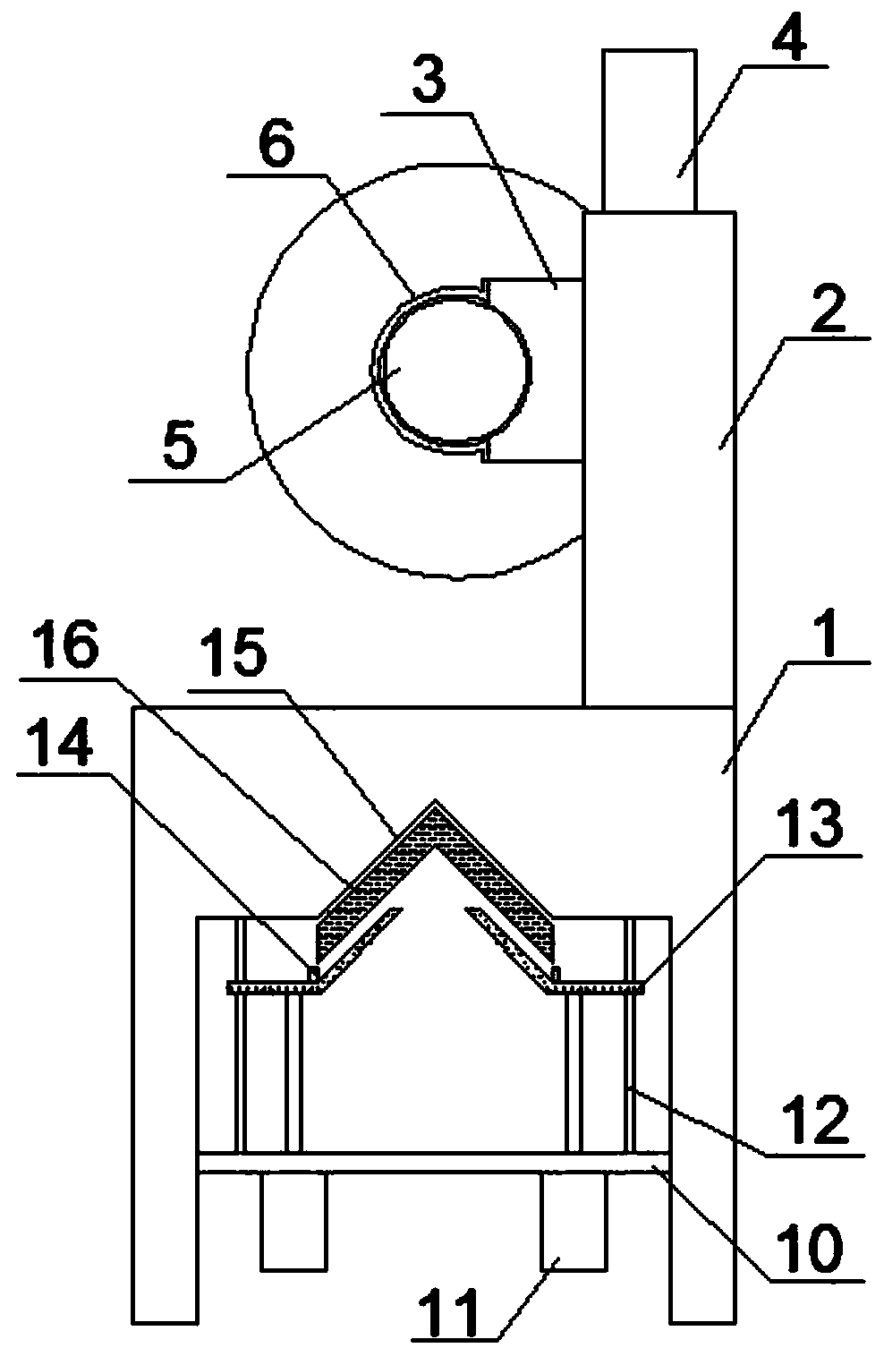
[0020] Such as Figure 1-3 As shown, the present invention discloses a cutting device for civil engineering components, including a frame 1, a clamping and pushing device, and the clamping and pushing device includes a support frame 7 and a beam plate 10, and the support frame 7 is fixedly connected to the frame 1 rear plane, the frame 7 is fixedly connected with a hydraulic cylinder 2 8, the piston rod of the hydraulic cylinder 2 8 is fixedly connected with a push plate 9, and the push plate 9 is facing the chute 15, and the beam plate 10 Fixedly connected to the inner wall of the lower end of the frame 1, the left and right ends of the beam plate 10 are respectively fixedly connected with a hydraulic cylinder group 11 and a guide rod 12, and each guide rod 12 is vertically slidably connected with a top plate 13, The two top plates 13 are fixedly connected to the two hydraulic cylinder groups 11 respectively, and a baffle plate 14 is fixedly connected to the top plate 13. The...


PUM


Abstract

The invention relates to the technical field of steel cutting equipment, in particular to a cutting device for civil engineering components. The cutting device comprises a rack and a clamping and pushing device. The clamping and pushing device comprises a supporting frame and a cross beam plate. The supporting frame is fixedly connected to the rear plane of the rack, and a second hydraulic cylinder is fixedly connected to the rack. A pushing plate is fixedly connected to a piston rod of the second hydraulic cylinder and directly faces a sliding groove. The cross beam plate is fixedly connectedto the inner side wall of the lower end of the rack. The left and right ends of the cross beam plate are each fixedly connected with a hydraulic cylinder set and a guiding rod. Each guiding rod is vertically slidably connected with a top plate, and the two top plates are fixedly connected with the two hydraulic cylinder sets correspondingly. Baffles are fixedly connected to the top plates, the V-shaped sliding groove is formed in the lower plane of the rack, and the included angle of the sliding groove is 90 degrees. The cutting device has the advantages that using is convenient, the labor intensity of workers is lowered, and the cutting efficiency and effect are improved.

Description

technical field [0001] The invention relates to the technical field of steel material cutting equipment, in particular to a civil engineering component cutting device. Background technique [0002] Civil engineering is a general term for the science and technology of building various land engineering facilities. It not only refers to the applied materials, equipment and technical activities such as survey, design, construction, maintenance, repair, etc., but also refers to the object of engineering construction; Various technical work such as survey, planning, design, construction, installation and maintenance of the buildings, structures and related supporting facilities of the project and the completed project entity. [0003] There are many kinds of components used in civil engineering, among which steel is the most used. There are various types of steel, such as I-beam, channel steel, angle steel, round steel, etc. Among them, angle steel has many uses; different civil ...

Claims


Application Information

Patent Timeline
Patent Type & Authority Patents(China)
IPC IPC(8): B23D79/00B23Q3/08B23Q7/00
CPCB23D79/00B23Q3/062B23Q3/082B23Q7/00
Inventor 彭勃
Owner JIANGXI UNIV OF SCI & TECH
Why Eureka
Try Eureka