Supercharge Your Innovation With Domain-Expert AI Agents!

Steel ball picking-up machine with double suction cups

A technology of suction cups and steel balls, which is applied to manipulators, chucks, manufacturing tools, etc., can solve the problems of troublesome workers, high cost, and falling of steel balls, and achieve the effect of convenient operation, simple structure, and convenient picking

Inactive Publication Date: 2018-12-18
宁国市金优机械配件有限公司
View PDF0 Cites 0 Cited by
  • Summary
  • Abstract
  • Description
  • Claims
  • Application Information

AI Technical Summary

Problems solved by technology

[0002] The steel ball picker is an auxiliary tool in the production or use of steel balls. The production process requires multiple processes. When the previous process is processed and the next process is reached, the steel balls need to be transferred to another workbench. In the process of moving, the steel balls fall down, causing a lot of trouble to the staff. Therefore, it is necessary to provide a double-suction cup steel ball pick-up machine. Its appearance can solve the above problems well. It is not only simple in structure, And easy to operate; Existing steel ball pick-up machine has certain drawbacks in use, at first, in use, most steel ball pick-up machines are electromagnetic, and cost is higher, has certain inconvenience, secondly, single The suction cup will cause a lot of trouble to use when it breaks down. In addition, during use, when the steel ball rolls to the corner, the steel ball picker cannot pick it up, which has certain disadvantages, which brings people's use process There are certain adverse effects, for this reason, we propose a double-sucker steel ball pick-up machine

Method used


Image

  • Steel ball picking-up machine with double suction cups
  • Steel ball picking-up machine with double suction cups
  • Steel ball picking-up machine with double suction cups

Examples


Embodiment Construction

[0016] In order to make the technical means, creative features, goals and effects achieved by the present invention easy to understand, the present invention will be further described below in conjunction with specific embodiments.

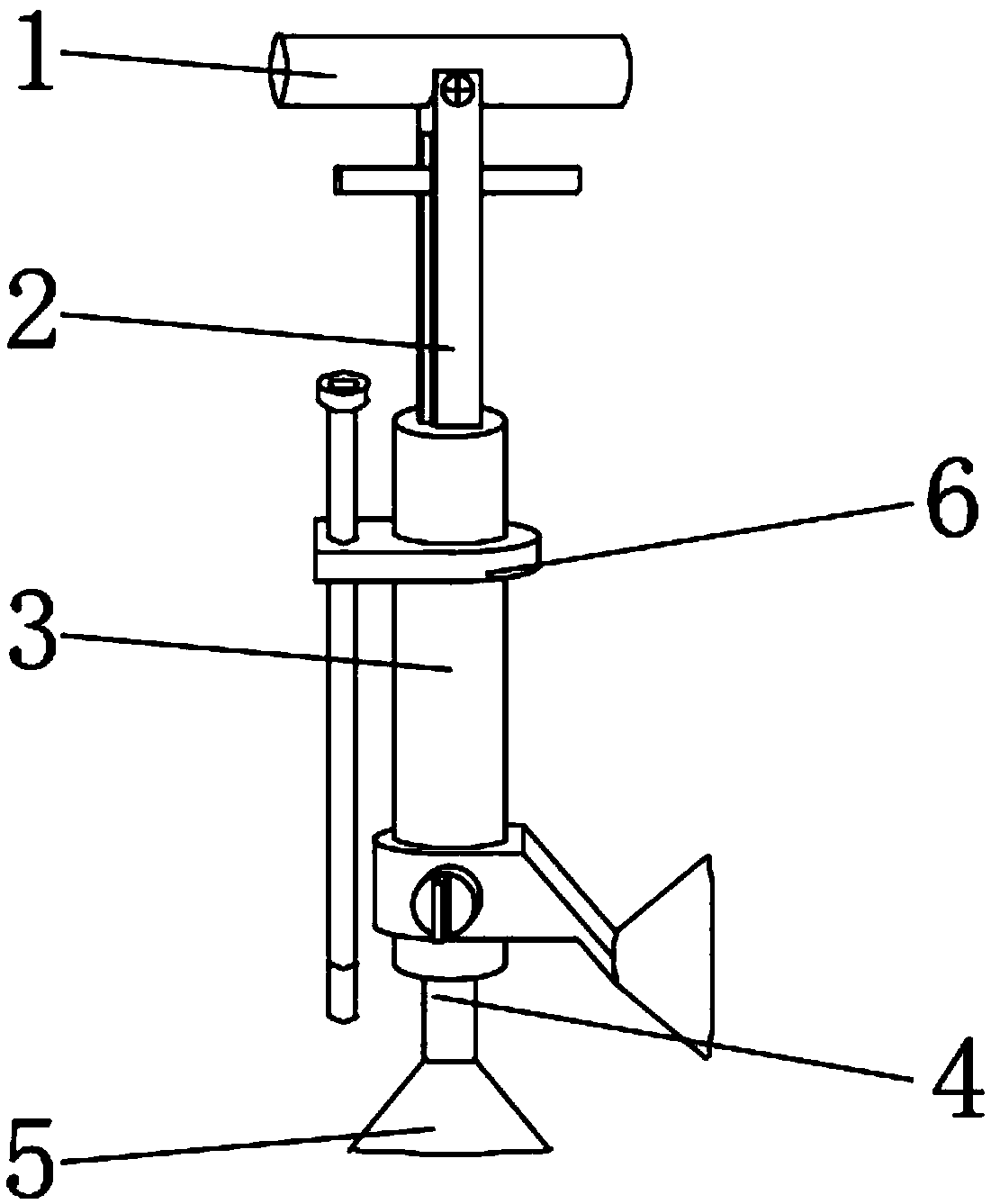
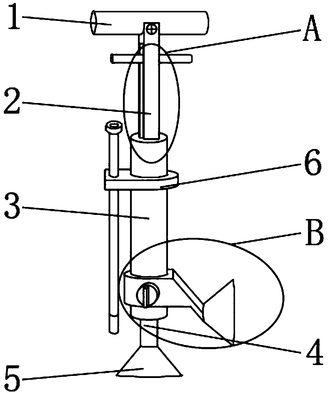
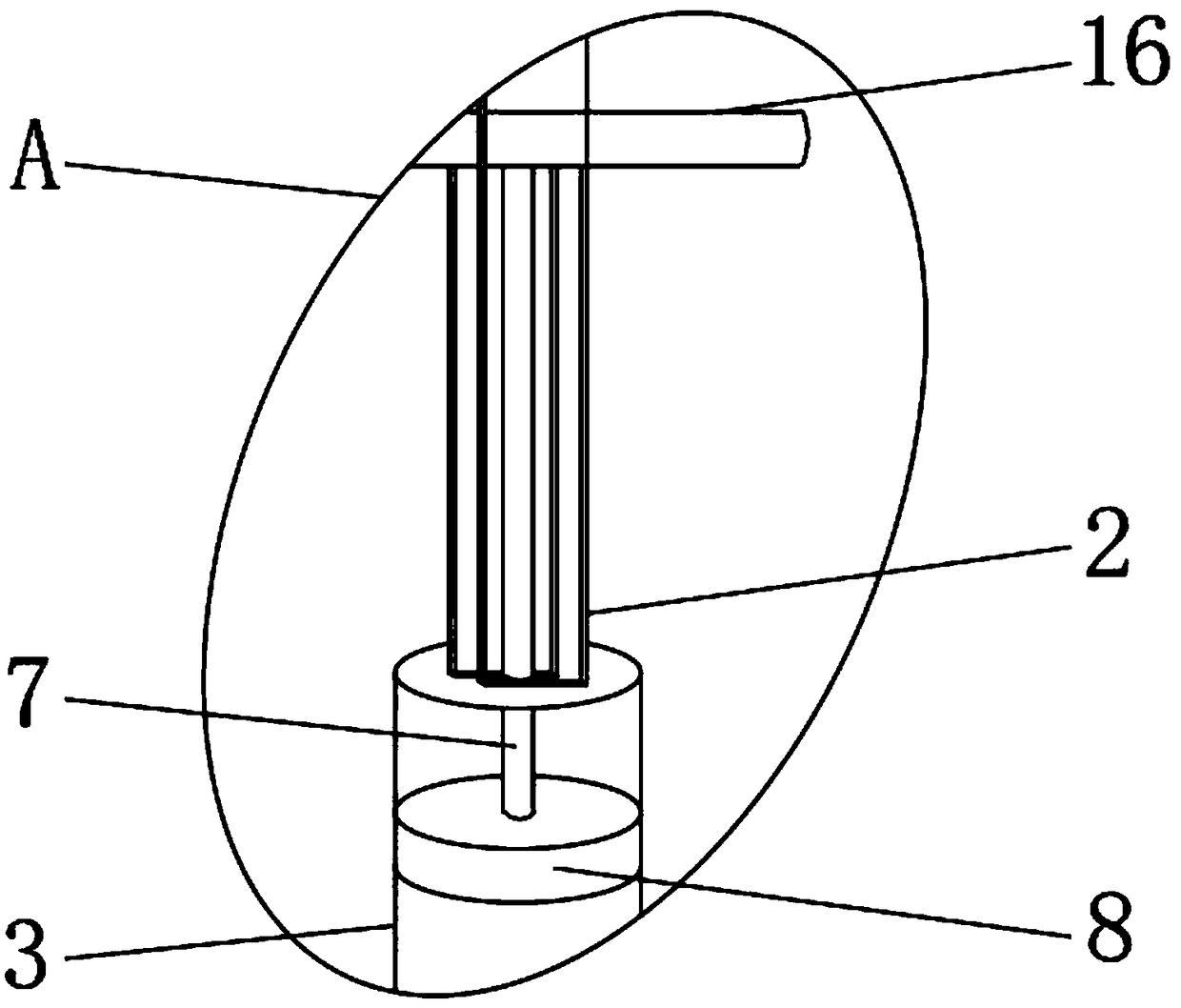
[0017] like Figure 1-5 As shown, a kind of double sucker steel ball pick-up machine of the present invention comprises grip bar 1, and the outer surface of the middle part of the lower end of grip bar 1 is fixedly equipped with chute bar 2, and the middle part of chute bar 2 is provided with push-pull bar 16, pushes A push rod 7 is fixedly installed on the outer surface of the lower end middle part of the pull rod 16, a sleeve 3 is fixedly installed on the lower end outer surface of the chute rod 2, a sliding part 8 is fixedly installed on the lower end outer surface of the push rod 7, and a sliding part 8 is fixedly installed on the upper outer surface of the sleeve 3. A fixing device 6 is fixedly installed, a collar 9 is fixedly installed on th...


PUM


Abstract

The invention discloses a steel ball picking-up machine with double suction cups. The steel ball picking-up machine comprises a holding rod. A sliding groove rod is fixedly mounted on the outer surface of the middle of the lower end of the holding rod, and a push-pull rod is arranged in the middle of the sliding groove rod. A push rod is fixedly mounted on the outer surface of the middle of the lower end of the push-pull rod, and a sleeve is fixedly mounted on the outer surface of the lower end of the sliding groove rod. A sliding part is fixedly mounted on the outer surface of the lower end of the push rod, and a fixing device is fixedly mounted on the outer surface of the upper end of the sleeve. A lantern ring is fixedly mounted on the outer surface of the lower end of the sleeve, and apipeline is fixedly mounted on the outer surface of the bottom of the sleeve. The rubber suction cup is fixedly mounted on the outer surface of the lower end of the pipeline. According to the steel ball picking-up machine with the double suction cups, the sliding part, the magnetic suction cup and threaded rods are arranged, steel balls can be sucked conveniently, the same effect can further be achieved through the magnetic suction cup, the steel balls can be guided out step by step through magnetic force, picking up is convenient, and the better using prospects are brought.

Description

technical field [0001] The invention relates to the field of steel ball picking machines, in particular to a steel ball picking machine with double suction cups. Background technique [0002] The steel ball picker is an auxiliary tool in the production or use of steel balls. The production process requires multiple processes. When the previous process is processed and the next process is reached, the steel balls need to be transferred to another workbench. In the process of moving, the steel balls fall down, causing a lot of trouble to the staff. Therefore, it is necessary to provide a double-suction cup steel ball pick-up machine. Its appearance can solve the above problems well. It is not only simple in structure, And easy to operate; Existing steel ball pick-up machine has certain disadvantages in use, at first, in use, most steel ball pick-up machines are electromagnetic, and cost is higher, has certain inconvenience, secondly, single When the sucker breaks down, it wil...

Claims


Application Information

Patent Timeline
IPC IPC(8): B25J1/04B25J1/00B25J15/06
CPCB25J1/04B25J1/00B25J15/06B25J15/0608B25J15/0616
Inventor 刘闻
Owner 宁国市金优机械配件有限公司
Features
  • R&D
  • Intellectual Property
  • Life Sciences
  • Materials
  • Tech Scout
  • Unparalleled Data Quality
  • Higher Quality Content
  • 60% Fewer Hallucinations
Learn More