Novel automatic perforating device

A punching device and automatic technology, applied in the direction of metal processing, etc., can solve the problems of difficult punching and processing of cardboard, damage of cardboard, time-consuming and laborious, etc., and achieve the effects of simple structure, easy operation, and improved running speed.

Inactive Publication Date: 2018-12-18
林仕长
View PDF0 Cites 3 Cited by
  • Summary
  • Abstract
  • Description
  • Claims
  • Application Information

AI Technical Summary

Problems solved by technology

[0002] The logistics industry is developing faster and faster around the world. The packaging and ordering of goods is a very important part of the logistics industry chain, and the packaging and ordering of goods is inseparable from the punching of cardboard. The punching process of cardboard is very difficult and there are many problems. The traditional punching method is time-consuming and laborious, the efficiency is extremely low, and it is easy to cause serious damage to the cardboard.

Method used


Image

  • Novel automatic perforating device
  • Novel automatic perforating device
  • Novel automatic perforating device

Examples


Embodiment Construction

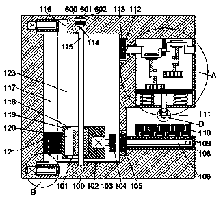
[0017] Such as Figure 1-5As shown, a new type of automatic punching device of the present invention includes a device main body 100, the device main body 100 is provided with an operation chamber 111 opening to the right, and a first slider 109 is slidably installed on the lower end surface of the operation chamber 111 , the upper end of the first slider 109 is fixed with an operation table 110, the first slider 109 is provided with a first rotating chamber with an opening to the left, and a leftward opening is rotatably installed in the first rotating chamber. The first threaded sleeve 108, the first threaded shaft 106 is threadedly installed in the first threaded sleeve 108, and the first transmission chamber located on the left side of the operation chamber 111 and extending upward is provided in the device main body 100 123, the first friction wheel 105 is installed in rotational cooperation between the first transmission chamber 123 and the operation chamber 111, and the...


PUM


Abstract

A novel automatic perforating device comprises a device body. An operating cavity with an opening rightward is formed in the device body, and a first siding block is slidably mounted on the lower endface of the operating cavity. An operating table is fixedly arranged at the upper end of the first sliding block, and a first rotating cavity with an opening leftward is formed in the first sliding block. A first threaded sleeve with an opening leftward is rotatably mounted in the first rotating cavity, and a first threaded shaft is mounted in the first threaded sleeve in a threaded-fit mode. A first transmission cavity which is located in the left side of the operating cavity and extends upwards is formed in the device body. A first friction wheel is mounted between the first transmission cavity and the operating cavity in a rotating-fit mode, and the right end of the first friction wheel and the left end of the first threaded shaft are fixedly matched. First sliding grooves are formed inthe inner walls of the left and lower sides of the first transmission cavity in a communicating mode correspondingly, second sliding blocks are slidably arranged in the first sliding grooves, and first motors are fixedly arranged in the left end walls of the first sliding grooves.

Description

technical field [0001] The invention relates to the technical field of fully automatic punching, in particular to a novel automatic punching device. Background technique [0002] The logistics industry is developing faster and faster around the world. The packaging and ordering of goods is a very important part of the logistics industry chain, and the packaging and ordering of goods is inseparable from the punching of cardboard. The punching process of cardboard is very difficult and there are many problems. The traditional punching method is time-consuming and laborious, the efficiency is extremely low, and it is easy to cause serious damage to the cardboard. Contents of the invention [0003] Aiming at the deficiencies of the above-mentioned technologies, the present invention proposes a novel automatic punching device. [0004] A new type of automatic punching device of the present invention comprises a device main body, an operation cavity with an opening to the right...

Claims


Application Information

Patent Timeline
Patent Type & Authority Applications(China)
IPC IPC(8): B26F1/00B26D5/14
CPCB26F1/00B26D5/14
Inventor 林仕长
Owner 林仕长
Why Eureka
Try Eureka