Continuous molding 3D printing equipment and operation method

A 3D printing and equipment technology, applied in the direction of metal processing equipment, 3D object support structure, manufacturing tools, etc., can solve the problems of large parts printing difficulty, slow reflow speed, difficult to take out parts, etc., to improve equipment adaptability to material types, The effect of fast forming speed and simple structure

Active Publication Date: 2020-06-19
XI AN JIAOTONG UNIV
View PDF10 Cites 0 Cited by
  • Summary
  • Abstract
  • Description
  • Claims
  • Application Information

AI Technical Summary

Problems solved by technology

However, they all adopt pull-up molding. Due to the gravity, the formed parts and the forming platform need a large combination density, which makes it very difficult to print large parts.
The use of sinking molding will have the following two problems: first, for high-speed printing of photosensitive resin, when the printing speed is high, the reflow speed of the photosensitive resin will be slow due to viscosity, and when the curing speed of the photosensitive resin is greater than that of the reflow Speed ​​means that the photosensitive resin cannot fill the gap between the molded part and the curing blind area in time, resulting in defects in the printed part
However, for continuous sinking 3D printing equipment, the stability of the curing blind zone depends on the concentration and pressure of the inhibitor. In order to accurately control the concentration and pressure of the inhibitor, it is necessary to have a sealed cabin above the molding cylinder or use closed molding Cylinder, so it is difficult to take out the parts with the traditional forming cylinder structure

Method used


Image

  • Continuous molding 3D printing equipment and operation method
  • Continuous molding 3D printing equipment and operation method
  • Continuous molding 3D printing equipment and operation method

Examples


Embodiment Construction

[0027] The present invention is further described below in conjunction with accompanying drawing:

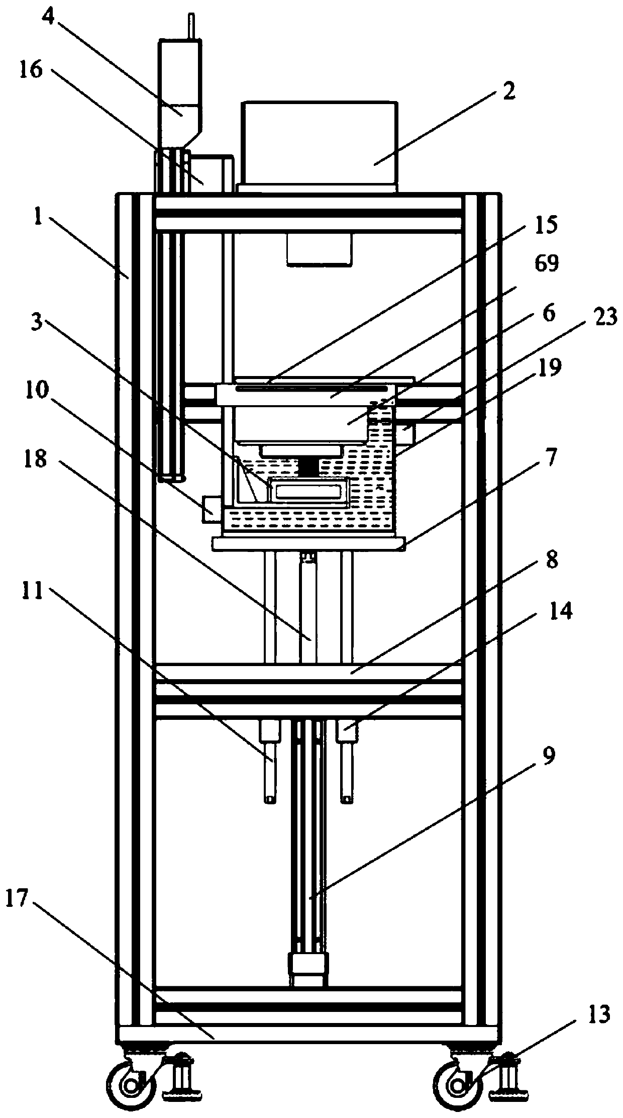
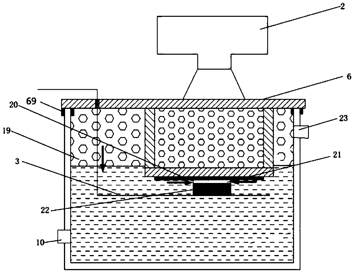
[0028] see Figure 1 to Figure 5 b, a continuous molding 3D printing equipment, including a frame 1, a molding cylinder 19, a molding cylinder lifting device, a light source 2, a molding platform 3, a molding platform lifting device, and a sealed cabin 6; the inside of the frame 1 is installed sequentially from top to bottom There are sealing cabin 6, molding cylinder 19 and molding cylinder lifting device, the molding cylinder lifting device drives the molding cylinder 19 to move up and down, when the molding cylinder 19 rises, the sealing cabin 6 is located inside the molding cylinder 19; the bottom of the sealing cabin 6 is provided with a molding platform 3. A forming platform lifting device is provided on the inner side of the frame 1, and the forming platform 3 is connected to the forming platform lifting device; the light source 2 is set on the top of the frame 1, and is ...


PUM


Abstract

Disclosed are continuous forming 3D printing equipment and an operation method thereof. According to the continuous forming 3D printing equipment, the forming position is located in liquid photosensitive resin, when printing is started, a forming cylinder lifting device drives a forming cylinder to rise so as to form a sealed cavity with a sealing cabin, then gas is injected into the forming cylinder, through the pressure generated by the gas in the forming cylinder, the backflow speed of the liquid photosensitive resin is increased, it is ensured that the liquid photosensitive resin can be supplemented in time during high-speed sprinting, it is ensured that the whole process can be conducted continuously, and adaptability of the equipment to materials is improved; by adopting a lifting forming cylinder structure, the forming cylinder can be lowered to the initial position after parts are printed, thus taking out of the parts is facilitated; additionally, the lifting forming cylinder is further replaced conveniently, the types of the materials adapted by the equipment are increased; in addition, a continuous sinking type rapid forming method can meet 3D printing of large and complex structural parts; and the continuous forming 3D printing equipment has the advantages of simple structure, high forming speed and high precision.

Description

technical field [0001] The invention belongs to the technical field of 3D printers, and in particular relates to continuous molding 3D printing equipment and an operation method. Background technique [0002] In recent years, the "continuous liquid interface manufacturing technology" (CLIP) developed in the United States based on the principle of oxygen inhibition has made the speed of 3D printing rapidly increase, and the speed can reach 500mm / h. Subsequently, the Institute of Physical Structure of the Chinese Academy of Sciences improved this technology, and the speed reached 650mm / h. However, they all adopt pull-up molding. Due to the gravity, the formed parts and the forming platform need a higher bonding density, which makes it very difficult to print large parts. The use of sinking molding will have the following two problems: first, for high-speed printing of photosensitive resin, when the printing speed is high, the reflow speed of the photosensitive resin will be s...

Claims


Application Information

Patent Timeline
Patent Type & Authority Patents(China)
IPC IPC(8): B29C64/135B29C64/20B29C64/255B29C64/245B29C64/307B29C64/393B33Y10/00B33Y30/00B33Y40/10B33Y50/02
CPCB29C64/135B29C64/20B29C64/245B29C64/255B29C64/307B33Y10/00B33Y30/00B33Y40/00
Inventor 段玉岗李晓刚章恪颜闫友璨
Owner XI AN JIAOTONG UNIV
Why Eureka
Try Eureka