Automatic arrangement and implantation device for hardware pins of power supply shell

A technology for automatic arrangement and implantation of devices, which is applied in the field of automatic arrangement of implantation devices for hardware PIN needles of power shells, can solve the problems of many subjective factors, high labor costs, and difficulty in guaranteeing product quality and accuracy, so as to ensure the feeding and stamping of materials. position, avoid implantation in place, improve efficiency and quality

Inactive Publication Date: 2018-12-18
HOWWEIH ELECTRONIC TECH (HUIZHOU) CO LTD
View PDF4 Cites 2 Cited by
  • Summary
  • Abstract
  • Description
  • Claims
  • Application Information

AI Technical Summary

Problems solved by technology

[0002] With the popularity of smart phones, mobile phone power plugs have spread to every household. At present, the production of mobile phone power shells is mostly plastic injection molding, and then inserting hardware PIN pins on the formed main body. The traditional way It relies on manual work to insert the metal PIN pins into the main body of the injection molding one by one, and then inserts the entire board with the help of a simple plate mold. Although this method of using the plate mold has improved the pin insertion speed to a certain extent, However, it still needs to be completed by hand using molds. For mass-produced mobile phone power supplies, it still requires more manpower to complete, and the labor cost is extremely high; Today, with the emphasis on efficiency and quality, this manual method of using molds to insert pins is becoming less and less suitable for the needs of market development.
[0003] At present, there are also pin insertion equipment that can realize automatic pin insertion. For example, the Chinese patent with the publication number of CN202917797U discloses an automatic pin insertion device, including a base and a needle insertion mechanism. The outer end of the needle insertion mechanism is provided with a needle pressing block. There is a first support block on the top, a second chute is arranged on the first support block, a first sliding block is arranged on the second chute, the first sliding block is fixed on the side of the pin insertion mechanism, and the first sliding block is close to the insertion One side of the needle mechanism is provided with a third chute, and a second sliding block is arranged in the third chute, and the end of the second sliding block close to the needle pressing block is provided with a slope surface for pressing the needle pressing block tightly, and the second sliding block There is a guide hole inclined at a certain angle on the block, and a guide post is set in the guide hole, and the guide post is fixedly connected with the limit rod set in the first slider; the automatic pin insertion device replaces the traditional manual pin insertion method , the pressing and pushing of the pins are completed continuously through one device, which improves the pin insertion efficiency, but the pin insertion equipment can only insert one hardware pin at a time, although the efficiency is improved compared with the traditional manual pin insertion, but Still unable to meet the requirements of modern high-speed production

Method used


Image

  • Automatic arrangement and implantation device for hardware pins of power supply shell
  • Automatic arrangement and implantation device for hardware pins of power supply shell
  • Automatic arrangement and implantation device for hardware pins of power supply shell

Examples


Embodiment

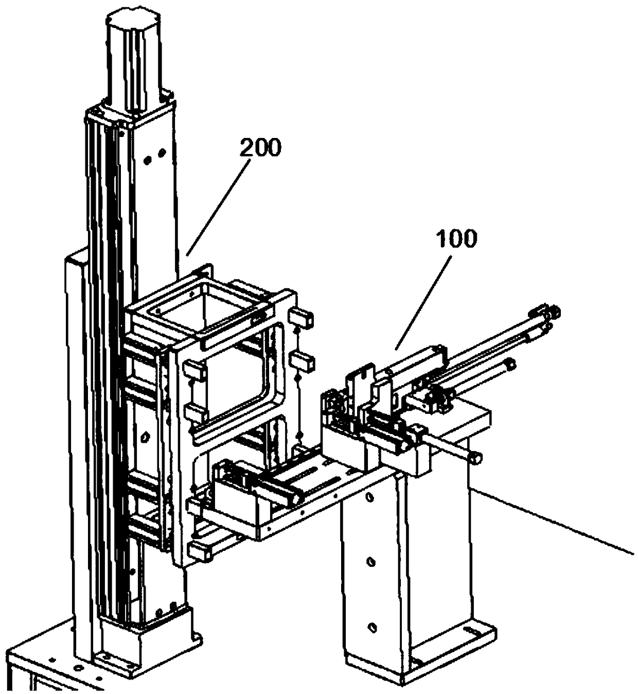
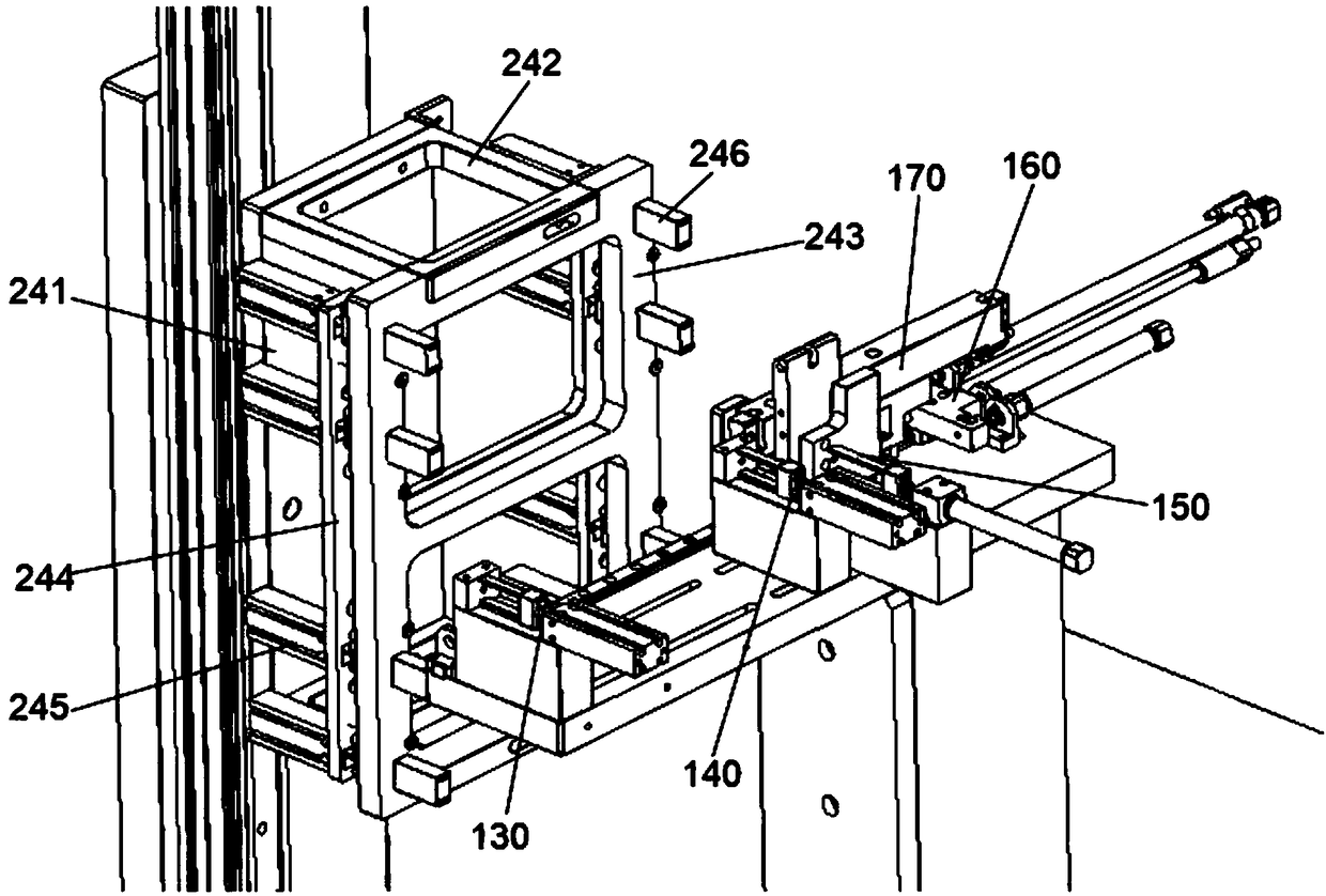
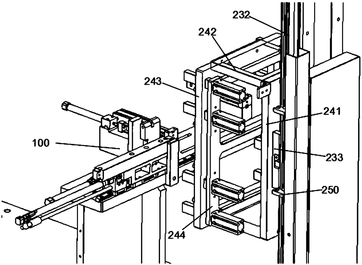
[0029] Embodiment: an implantation device for automatic arraying of hardware PIN pins of a power supply shell.

[0030] refer to Figure 1 to Figure 10 As shown, a power shell hardware PIN pin automatic arrangement implantation device, including:

[0031] Feeding mechanism 100; said feeding mechanism 100 includes a support frame 110; a mounting plate 120 installed on the top of the support frame 110, the front side of the top of the mounting plate 120 is equipped with a linear guide rail 161 arranged laterally along the mounting plate 120, the The linear guide rail 161 extends from the left side to the right side of the mounting plate 120, and limit blocks are arranged on the left and right end sides of the linear guide rail 161 to limit the maximum moving distance of the left and right end sides of the linear guide rail 161;

[0032] The sliding feeding mold 170 installed on the linear guide rail 161, the sliding feeding mold 170 is used for the transition to the movement of...


PUM


Abstract

The invention provides an automatic arrangement and implantation device for hardware pins of a power supply shell. The automatic arrangement and implantation device comprises a feeding mechanism and adischarging mechanism, wherein the discharging mechanism is arranged in front of the feeding mechanism. The feeding mechanism comprises a support frame, an installation plate, a sliding feeding die,a transverse driving device, a positioning feeding device, a feeding baffle, a first punching device and a second punching device. The discharging mechanism comprises a bottom supporting block, a rearsupporting plate, a linear driving module and a discharging die. The linear driving module is installed on the bottom supporting block and the rear supporting plate. The discharging die is fixed to the linear driving module. Through the cooperation between the first punching device, the second punching device, the positioning feeding device, the transverse driving device, the sliding feeding dieand the feeding baffle of the feeding mechanism and the linear driving module and the discharging die of the discharging mechanism, the automatic positioning feeding, arrangement and implantation of the hardware pins can be realized in the production of the power supply shell, one-time implantation of a plurality of groups of hardware pins can be realized, and therefore the implantation efficiencyof the hardware pins is greatly improved.

Description

technical field [0001] The invention relates to the technical field of automatic processing equipment for power supplies, in particular to a device for automatically arranging and implanting hardware PIN pins of a power supply shell. Background technique [0002] With the popularity of smart phones, mobile phone power plugs have spread to every household. At present, the production of mobile phone power shells is mostly plastic injection molding, and then inserting hardware PIN pins on the formed main body. The traditional way It relies on manual work to insert the metal PIN pins into the main body of the injection molding one by one, and then inserts the entire board with the help of a simple plate mold. Although this method of using the plate mold has improved the pin insertion speed to a certain extent, However, it still needs to be completed by hand using molds. For mass-produced mobile phone power supplies, it still requires more manpower to complete, and the labor cost...

Claims


Application Information

Patent Timeline
Patent Type & Authority Applications(China)
IPC IPC(8): B29C65/64B29C65/78
CPCB29C65/64B29C65/7805B29C65/7841B29C65/7858B29C66/742B29C66/863
Inventor 马树根王辉
Owner HOWWEIH ELECTRONIC TECH (HUIZHOU) CO LTD
Why Eureka
Try Eureka