Implanting device and method

A technology for implanting devices and installing components, which is applied in the field of anti-counterfeiting ID implanting devices for concrete test blocks, can solve problems such as increased construction unit cost, poor operability, and easy damage of two-dimensional code labels, so as to improve the implantation success rate and Productivity, Improving Implantation Efficiency, and Ease of Work

Pending Publication Date: 2020-07-17
四川广聚其力电子科技有限公司
View PDF0 Cites 1 Cited by
  • Summary
  • Abstract
  • Description
  • Claims
  • Application Information

AI Technical Summary

Problems solved by technology

[0007] 3) The cost of RFID chips is relatively high, and a large number of uses will increase the cost of the construction unit, which will cause great obstacles to the comprehensive promotion and use
[0012] 3) The concrete test block is made of cement, stones, etc., the QR code label is easily damaged, and the information cannot be guaranteed to be recognized normally
[0015] 1) The inspection unit is required to take comparative photos under the same conditions, which is difficult to do. The concrete was photographed in an unsolidified state, and then the concrete needs to go through a standard curing period of 28 days. During this period, the labels on the concrete and the concrete The outer surface will change accordingly, so the outer surface and label of the test block obtained by the testing unit are very different from the outer surface and label in the unsolidified state, so its operability is not strong
[0016] 2) The identification label on the exposed surface of the concrete also has the risk of artificial replacement
[0017] To sum up, it can be seen that the current concrete test block anti-counterfeiting supervision scheme cannot achieve efficient and comprehensive anti-counterfeiting supervision, and there is a large risk that the concrete test block will be replaced illegally

Method used


Image

  • Implanting device and method
  • Implanting device and method
  • Implanting device and method

Examples


Embodiment Construction

[0053] In order to make the objectives, technical solutions, and advantages of the present invention clearer, the present invention will be further described in detail below through specific embodiments with reference to the accompanying drawings. It should be understood that the specific embodiments described here are only used to explain the present invention, but not to limit the present invention.

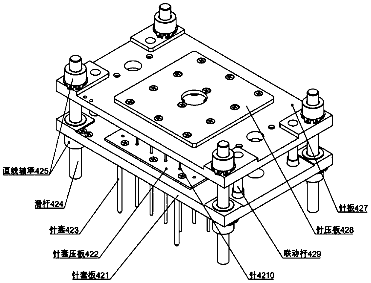
[0054] According to an embodiment of the present invention, the present invention provides an implantation device for implanting an object to be implanted into a carrier to improve implantation efficiency and avoid the problems of low efficiency and high error rate faced by manual operation. The implantation device includes a needle cover assembly, and the needle cover assembly includes a needle plate, a needle cover plate, and a sliding rod. Wherein, the needle plate is coupled with the slide bar to move reciprocally along the slide bar; the needle cover plate is arranged opposit...


PUM


Abstract

The invention provides an implanting device which is used for implanting an object to be implanted into a corresponding bearing object and comprises a needle sleeve assembly. The needle sleeve assembly comprises a needle plate, a needle sleeve plate and a sliding rod, wherein the needle plate is coupled with the sliding rod so as to reciprocate along the sliding rod; the needle sleeve plate and the needle plate are oppositely arranged in parallel, and the needle sleeve plate is coupled with the sliding rod so as to reciprocate along the sliding rod. The needle plate is used for fixing a plurality of needles, the needle sleeve plate is used for fixing a plurality of needle sleeves, each needle sleeve corresponds to one needle on the needle plate in position, and when the needle plate movesalong the sliding rod relative to the needle sleeve plate, the needles penetrate through the needle sleeves so as to implant a plurality of objects to be implanted into corresponding bearing objects.According to the implanting device, the source code magnetic body can be automatically implanted into the concrete test block at a time, the strength of the concrete test block is not affected, the array arrangement rule of the source code magnetic body corresponding to the anti-counterfeiting ID is not damaged, and the implantation success rate and the production efficiency are greatly improved.

Description

Technical field [0001] The present invention relates to the field of construction engineering quality supervision and detection, in particular to an auxiliary device and method for the supervision and management of the authenticity and uniqueness of concrete test block samples, and more specifically, to a concrete test block anti-counterfeiting ID implant device And method. Background technique [0002] In the field of construction, in order to supervise the quality of concrete entities, my country currently uses concrete specimens to be produced while pouring concrete entities as test pieces, and the construction unit sends these concrete test pieces to the inspection unit for testing. The concrete test block reflects the strength of the concrete entity to a certain extent, and is also the main basis for the quality evaluation of concrete. Therefore, the monitoring and management of the concrete test block is of great significance to ensure the quality of the concrete entity. I...

Claims


Application Information

Patent Timeline
Patent Type & Authority Applications(China)
IPC IPC(8): G01N1/28G01N1/36G01N33/38G06K17/00G06Q50/08G01S19/42
CPCG01N1/28G01N1/36G01N33/383G01N2001/366G01S19/42G06K17/0029G06Q50/08
Inventor 彭可
Owner 四川广聚其力电子科技有限公司
Why Eureka
Try Eureka