

Efficient CNC glass feeding and discharging machine
A high-efficiency, feeder technology, used in conveyor objects, furnaces, lighting and heating equipment, etc., can solve the problem of consistency, controllability, efficiency cannot be guaranteed, abnormal physical conditions of employees, low utilization of CNC machine tools, etc. problems, to achieve the effect of improving processing yield, eliminating safety hazards, saving space and manpower
- Summary
- Abstract
- Description
- Claims
- Application Information
AI Technical Summary
Problems solved by technology
Method used
Image

Examples
Embodiment Construction
[0052] The present invention will be described in detail below in conjunction with the accompanying drawings and specific embodiments.
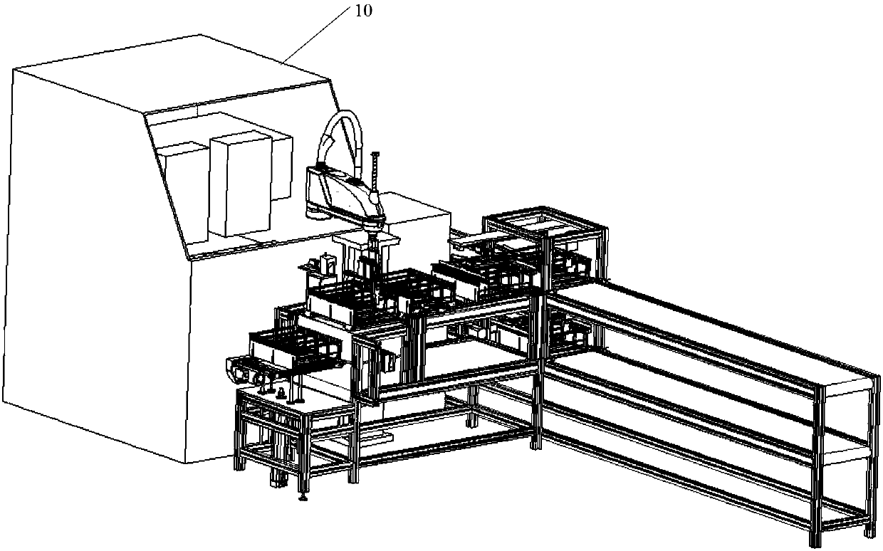
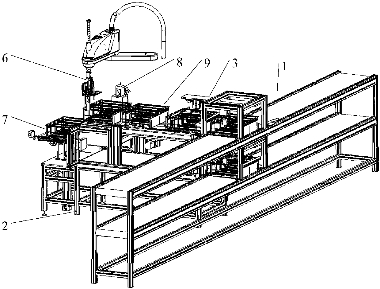
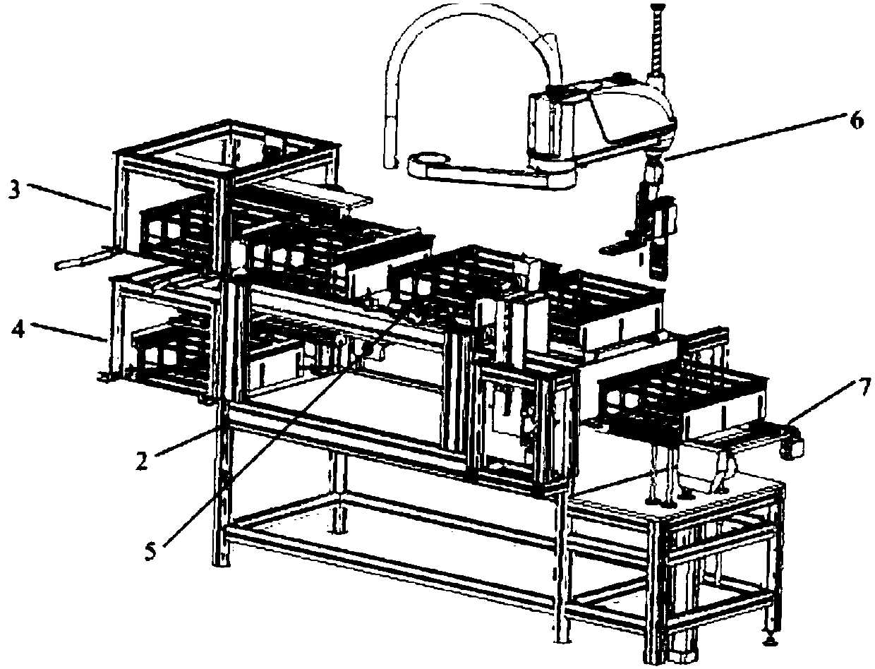
[0053] refer to Figures 1 to 8 As shown, the present invention provides a CNC glass high-efficiency loading and unloading machine, including a first transmission device 1, a second transmission device 2, a first material frame clamping device 3, a second material frame clamping device 4, a positioning device 5, Manipulator device 6, lifting and transferring device 7; the first conveying device 1 and the second conveying device 2 both include an upper belt line and a lower belt line, and the first conveying device 1 and the second conveying device 2 are vertically arranged; A material frame clamping device 3 is used to clamp the material frame from the upper belt line of the first conveying device 1 to the upper belt line of the second conveying device 2; the positioning device 5 is installed on the upper belt line of the second conveying dev...
PUM
 Abstract
Description
Claims
Application Information