A splice truck front bumper

A front bumper, splicing technology, applied in the direction of bumpers, vehicle parts, vehicle safety arrangements, etc., can solve the problems of easily damaged car front, poor anti-collision effect of bumpers, difficult to disassemble and replace, etc., to achieve compact structure and reduce impact. The effect of strength and easy installation

Active Publication Date: 2018-12-18
HEFEI DONGSHENG AUTO PARTS CO LTD
View PDF5 Cites 3 Cited by
  • Summary
  • Abstract
  • Description
  • Claims
  • Application Information

AI Technical Summary

Problems solved by technology

[0004] The purpose of the present invention is to provide a spliced ​​truck front bumper, which has the advantages of more comprehensive protection and convenient disassembly and installation, in order to solve the above-mentioned problem that the side bumper has poor anti-collision effect and is easy to damage the front of the car and the integral type is not easy to disassemble and replace.

Method used


Image

  • A splice truck front bumper
  • A splice truck front bumper
  • A splice truck front bumper

Examples


Embodiment 1

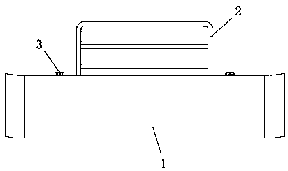
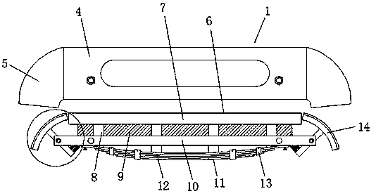
[0023] see Figure 1-4 As shown, a spliced ​​truck front bumper includes a protective case 1, an anti-collision bar 2 and a bumper body 6, and the top of the protective case 1 is equipped with an anti-collision bar 2, and the protective case 1 is composed of a front fender 4 and a side shield The protective shell 1 is composed of a bumper body 6, and the inside of the bumper body 6 is provided with a front beam 7, a side beam 14 and a fixed plate 10, and one side of the front beam 7 is provided with several connecting rods 8, and the connecting rods 8 The outer wall of the fixed plate 10 is socketed, and an energy-absorbing layer 9 is arranged between the fixed plate 10 and the front beam 7. A buffer plate 11 is installed at one end of the connecting rod 8 through the fixed plate 10. The buffer plate 11 is composed of several steel bars 12, and several The two steel bars 12 are attached and fixed to each other by binding straps 13, the inside of the side beam 14 is provided wi...

Embodiment 2

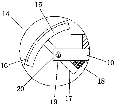
[0025] In addition, refer to Figure 1-4 , different from the above-mentioned embodiment 1, the interior of the installation groove 21 is equipped with a rotating screw rod 19, the installation rod 17 is rotationally connected with the installation groove 21 through the rotating rod screw rod 19, and the rotating screw rod 19 passes through one end of the installation groove 21 top The nut 20 and the thread 20 can be tightened so that the installation rod 17 cannot be easily rotated, so that part of the impact force received by the side beam 14 is used to rotate the installation rod 17 to offset and disappear, and part of it is offset by the spring 18, so that the side beam 14 is shock-resistant The capacity is improved. The outer wall of the support beam 15 inside the side beam 14 is in an arc-shaped structure, and the specifications of the support beam 15 match the side baffle 5. A rubber layer 16 is laid between the support beam 15 and the side baffle 5. The curved side The...


PUM


Abstract

The invention discloses a spliced truck front bumper, comprising a protective shell, an anti-collision bar, a fixing bolt, a front baffle plate, a side baffle plate, a bumper body, a front beam, a connecting rod, an energy absorbing layer, a fixing plate, a buffer plate, a steel bar, a strapping belt, a side beam, a support beam, a rubber layer, a mounting rod, a spring, a rotating screw rod, a nut, a mounting groove and a connecting hole. By providing a bumper body inside the protective housing, and the bumper body is composed of a front member and two side members, so that both the front andside shields of the shield protect the truck head in the event of a collision, The side member is not connected with the front member, and the side member is inclined to both ends of the fixing platethrough the mounting rod, so that the front member is not affected when the truck head is hit on the side, and the mounting rod can be rotated with the fixing plate through the rotating screw rod, and the tail end of the mounting rod is connected with the back of the fixing plate through a spring, so that the side member has cushioning capacity. The invention has the characteristics of good frontside anti-collision effect.

Description

technical field [0001] The invention relates to a front bumper, in particular to a spliced ​​truck front bumper, which belongs to the technical field of auto parts. Background technique [0002] The car bumper is a safety device that absorbs and slows down the external impact and protects the front and rear of the car body. The car bumper is located in most areas of the front and rear of the car. It is designed to avoid the impact of the external damage of the vehicle on the vehicle safety system. They have the ability to reduce injuries to drivers and passengers during high-speed collisions, and now more and more bumpers are designed for pedestrian protection. [0003] The existing bumper still has certain defects when buffering the impact. The front end of the existing bumper has good anti-collision effect, but the areas on both sides have poor anti-collision ability, and the driver will habitually Turning the steering wheel makes the side front of the front of the car co...

Claims


Application Information

Patent Timeline
IPC IPC(8): B60R19/04B60R19/18
CPCB60R19/04B60R19/18B60R2019/1833
Inventor 王友松韩德良袁德宝张玉成
Owner HEFEI DONGSHENG AUTO PARTS CO LTD
Why Eureka
Try Eureka