A logistics box locking device

A logistics box and box lock technology, applied in the field of logistics boxes, can solve the problems of increasing the labor intensity of the staff, adversely affecting the working efficiency of the staff, inconvenient handling, etc., and achieve the effects of convenient and rapid identification, flexible twitching, and avoidance of handling errors.

Active Publication Date: 2021-08-31
一汽物流(长春陆顺)储运有限公司
View PDF0 Cites 0 Cited by
  • Summary
  • Abstract
  • Description
  • Claims
  • Application Information

AI Technical Summary

Problems solved by technology

[0002] Logistics boxes, also known as turnover boxes, are widely used in machinery, automobiles, home appliances, light industry, electronics and other industries. They are resistant to acids, alkalis, oils, non-toxic and tasteless. They can be used to hold food, etc. They are easy to clean and turn over parts. , Stacked neatly, easy to manage, its reasonable design, excellent quality, suitable for transportation, distribution, storage, circulation processing and other links in the factory logistics, the logistics box will use the locking device to fix the box body and box cover when in use Together, most of the existing locking devices are simple buckles, which are easily loosened due to shaking during transportation, resulting in scattered items, which is not only inconvenient for subsequent handling, but also increases the labor intensity of the staff. Cause damage and loss of items, poor practicability, in addition, most locking devices need to be opened and closed manually, the operation is cumbersome, and it is not conducive to improving the work efficiency of the staff

Method used


Image

  • A logistics box locking device
  • A logistics box locking device
  • A logistics box locking device

Examples


Embodiment Construction

[0023] The following will clearly and completely describe the technical solutions in the embodiments of the present invention with reference to the accompanying drawings in the embodiments of the present invention. Obviously, the described embodiments are only some, not all, embodiments of the present invention. Based on the embodiments of the present invention, all other embodiments obtained by persons of ordinary skill in the art without making creative efforts belong to the protection scope of the present invention.

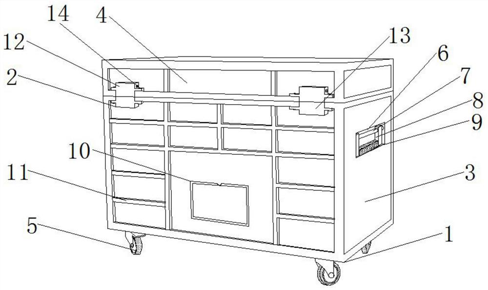
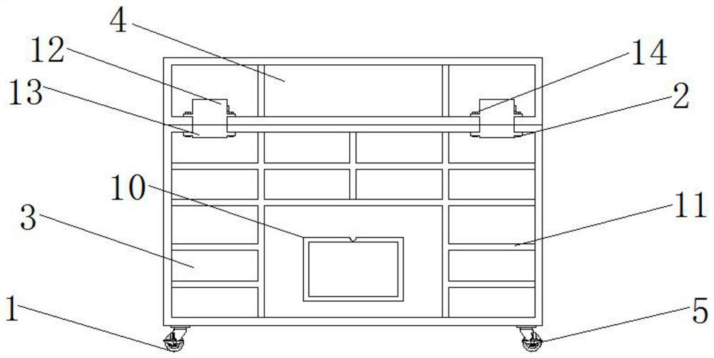
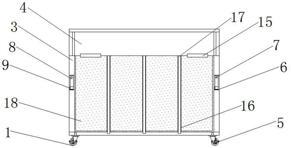
[0024] see Figure 1-6 , the present invention provides a technical solution: a logistics box locking device, including a logistics box 1, a device body 2, a box body 3, a box cover 4, casters 5, a groove 6, a rotating shaft 7, a handle 8, and a rubber layer 9 , label plate 10, reinforcing rib 11, locking box 12, locking seat 13, fixing screw 14, hinge 15, chute 16, baffle plate 17, sponge 18, R280 motor 19, rotating shaft 20, shaft seat 21, Left belt 22, lef...


PUM


Abstract

The invention discloses a logistics box locking device. Locking seats are installed on both sides of the front top of the box body. The left side inside the locking seat is provided with a left threaded hole, and the right side inside the locking seat is provided with a right threaded hole. , There are hinges installed on both sides of the top of the back of the box, a box cover is installed on the top of the hinge, a locking box is installed on both sides of the front bottom of the box cover, an R280 motor is installed on the top of the inside of the locking box, and the bottom of the R280 motor The end of the rotating shaft is fixedly connected with a rotating shaft, the bottom end of the rotating shaft is equipped with a shaft seat, the left side of the rotating shaft is covered with a left belt, one end of the left belt is installed with a left screw, the top of the left screw is equipped with a left guide sleeve, and the top of the rotating shaft is equipped with a left guide sleeve. The right side sleeve is provided with a right belt, one end of the right belt is installed with a right screw rod, and the top of the right screw rod is installed with a right guide sleeve. The left screw rod and the left threaded hole of the present invention are used in conjunction with each other, and the right screw rod and the right threaded hole are used in conjunction with each other. , The double locking setting greatly enhances the locking effect of the device body and further improves its practicability.

Description

technical field [0001] The invention relates to the technical field of logistics boxes, in particular to a logistics box locking device. Background technique [0002] Logistics boxes, also known as turnover boxes, are widely used in machinery, automobiles, home appliances, light industry, electronics and other industries. They are resistant to acids, alkalis, oils, non-toxic and tasteless. They can be used to hold food, etc. They are easy to clean and turn over parts. , Stacked neatly, easy to manage, its reasonable design, excellent quality, suitable for transportation, distribution, storage, circulation processing and other links in the factory logistics, the logistics box will use the locking device to fix the box body and box cover when in use Together, most of the existing locking devices are simple buckles, which are easily loosened due to shaking during transportation, resulting in scattered items, which is not only inconvenient for subsequent handling, but also incre...

Claims


Application Information

Patent Timeline
Patent Type & Authority Patents(China)
IPC IPC(8): B65D55/02
CPCB65D55/02
Inventor 不公告发明人
Owner 一汽物流(长春陆顺)储运有限公司
Why Eureka
Try Eureka