Cable-stayed bridge pylon reinforcement skeleton manufacture method
A cable-stayed bridge cable tower and steel skeleton technology, applied to bridges, bridge parts, bridge construction, etc., can solve problems such as short construction time, extended construction period, and long concrete curing time, so as to improve production efficiency and reduce misoperation Effect
- Summary
- Abstract
- Description
- Claims
- Application Information
AI Technical Summary
Problems solved by technology
Method used
Image

Examples
Embodiment 1
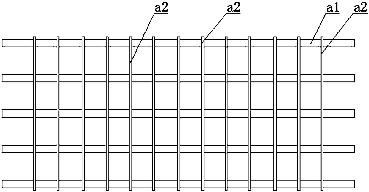
[0047] Such as figure 1 , 2 As shown in , 3, a steel bar skeleton includes a plurality of main bars a1 parallel to each other, all of the main bars a1 are distributed in a rectangular array, and a plurality of stirrup cages a2 are arranged on the main bars a1 along its length direction, Each of the stirrup cages a2 is connected to all the main reinforcements a1 at the same time;
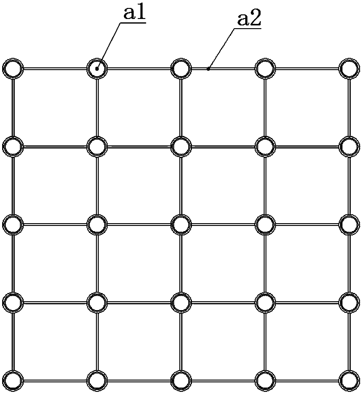
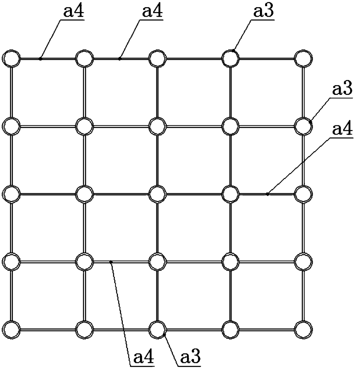
[0048] The main reinforcement collar a3 corresponding to the main reinforcement a1 is arranged on the stirrup cage a2, so that all the main reinforcement collars a3 of each stirrup cage a2 are also distributed in a rectangular array, The main reinforcement rings a3 in two adjacent rows and two adjacent columns are respectively connected by a stirrup bar a4, and the two ends of the stirrup bar a4 are respectively connected with the corresponding main reinforcement ring a3; all the stirrup bars The ribs a4 form the stirrup cage a2 in a grid shape, and the main rib collars a3 are located at nodes of t...
Embodiment 2
[0052] A method for manufacturing a steel bar skeleton of a cable-stayed bridge cable tower based on embodiment 1, comprising the following steps:
[0053] Step 1, setting the stirrup cage a2;
[0054]The stirrup cage a2 includes the main reinforcement rings a3 distributed in a rectangular array in the same plane, the centerlines of the main reinforcement rings a3 are parallel to each other, two adjacent rows and two adjacent rows of the main reinforcement rings A3 are respectively connected by a stirrup strip a4, and the two ends of the stirrup strip a4 are respectively connected with the corresponding main reinforcement ring a3;
[0055] Step 2, setting the stirrup positioning device;
[0056] Such as Figure 4-11 As shown, the stirrup positioning device includes a lower base plate b1, on which a plurality of positioning sleeves b2 are vertically arranged, and the positioning sleeves b2 are distributed in a rectangular array on the lower base plate b1, and the positioning ...
PUM
 Abstract
Description
Claims
Application Information
 - R&D
- Intellectual Property
- Life Sciences
- Materials
- Tech Scout
- Unparalleled Data Quality
- Higher Quality Content
- 60% Fewer Hallucinations
Browse by: Latest US Patents, China's latest patents, Technical Efficacy Thesaurus, Application Domain, Technology Topic, Popular Technical Reports.
© 2025 PatSnap. All rights reserved.Legal|Privacy policy|Modern Slavery Act Transparency Statement|Sitemap|About US| Contact US: help@patsnap.com