Eureka AIR delivers breakthrough ideas for toughest innovation challenges, trusted by R&D personnel around the world.

Flange type connection structure between top of steel pipe pile and I-beam cross-beam

A technology for connecting structures and I-beams, which is applied in basic structure engineering, sheet pile walls, buildings, etc., to achieve the effect of improving the reuse rate, improving economic benefits and simple operation.

Pending Publication Date: 2018-12-18
ROAD & BRIDGE INT
View PDF4 Cites 2 Cited by
  • Summary
  • Abstract
  • Description
  • Claims
  • Application Information

AI Technical Summary

Problems solved by technology

[0003] The purpose of the present invention is to provide a flange-type connection structure between the top of the steel pipe pile and the I-beam beam in view of the defects existing in the welding structure of the top of the steel pipe pile and the I-beam beam, and the steel pipe pile can be realized without welding. The stable connection of piles and beams improves construction efficiency and does not cause damage to steel pipe piles and beams

Method used


Image

  • Flange type connection structure between top of steel pipe pile and I-beam cross-beam
  • Flange type connection structure between top of steel pipe pile and I-beam cross-beam
  • Flange type connection structure between top of steel pipe pile and I-beam cross-beam

Examples


Embodiment Construction

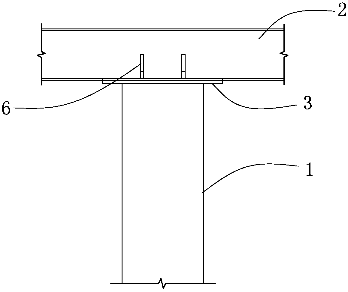
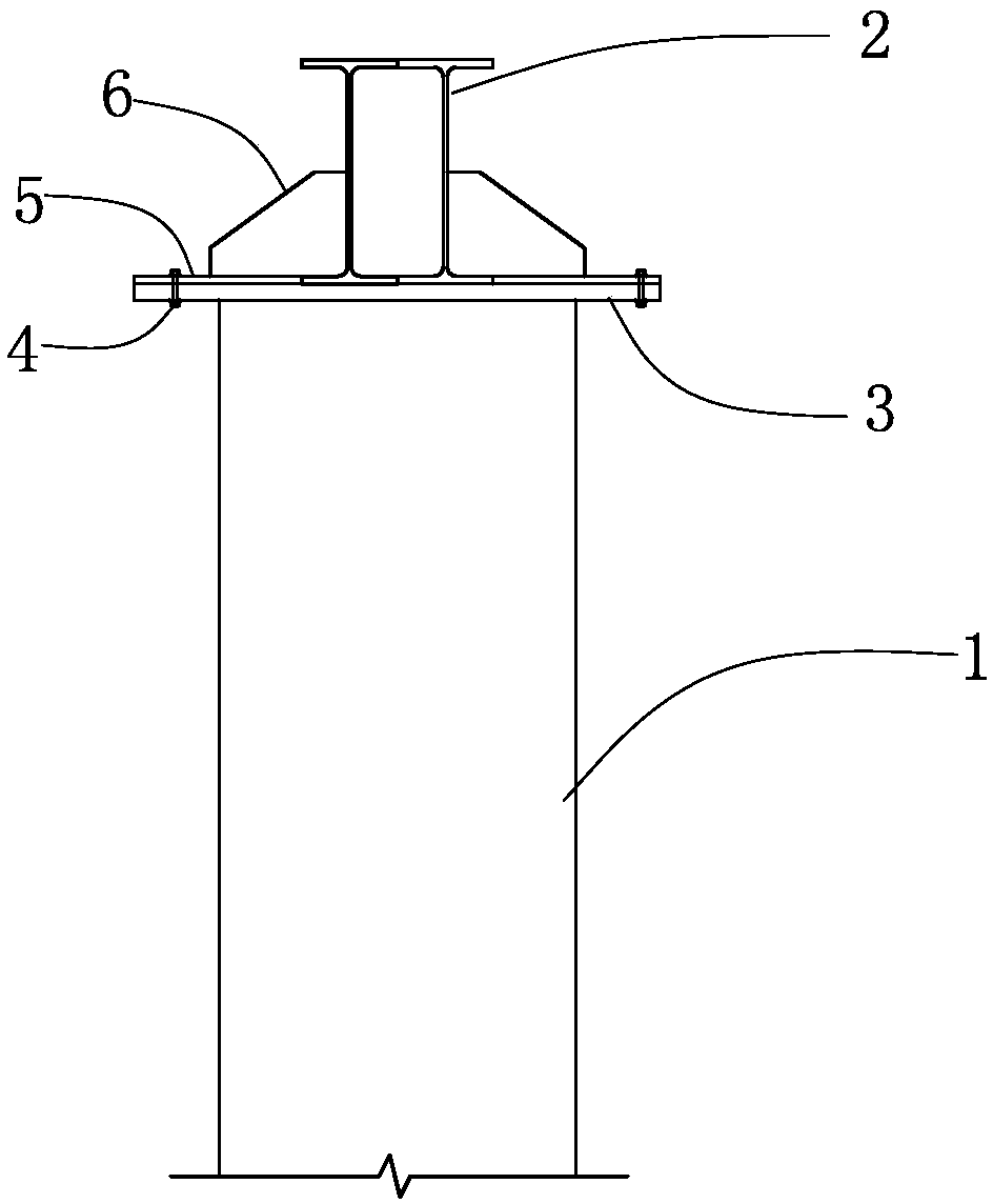
[0014] Such as figure 1 , figure 2 , image 3 As shown, the present invention includes a steel pipe pile 1 and an I-beam beam 2 horizontally arranged on the top of the steel pipe pile. The flange plate on the other side is set downward; the top of the steel pipe pile 1 is welded with a fixed flange 3 arranged horizontally, and the structure of the fixed flange is as follows: Figure 4 As shown, screw holes are preset on opposite sides of the fixing flange 3 . The fixed flange 3 connects the two limiting flanges 5 with bolts 4 through screw holes.

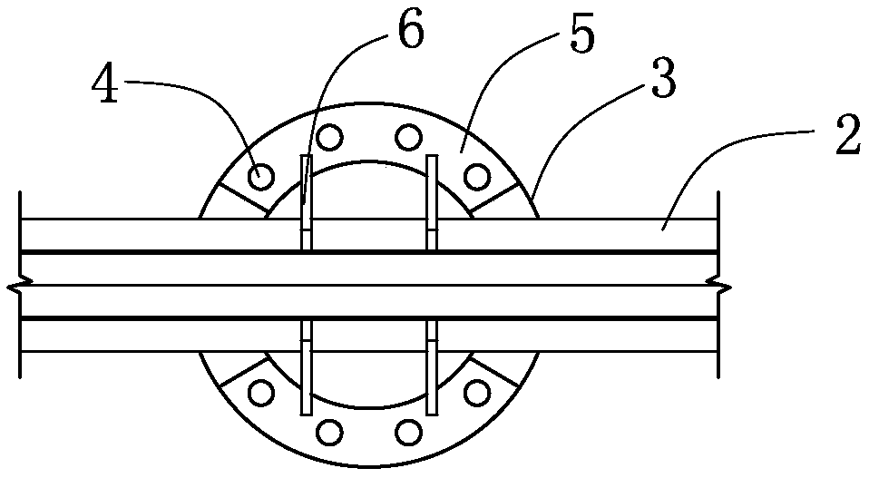
[0015] Such as Figure 5 , Image 6 , Figure 7 As shown, each limit flange 5 is a section of arc-shaped steel plate, and each limit flange 5 is provided with an inner arc edge and an outer arc edge, and its radian is equal to the outer peripheral arc radian of the fixed flange 3. Two limit methods 5 The inner arc sides of the two limit flanges are arranged oppositely, and the screw holes corresponding to the fixed flanges a...


PUM


Abstract

The invention provides a flange type connection structure between the top of a steel pipe pile and an I-beam cross-beam. The flange type connection structure between the top of the steel pipe pile andthe I-beam cross-beam is used for erection of a steel pipe pile bracket. A fixed flange is weld to the top of the steel pipe pile, the I-beam cross beam of the fixed flange is horizontally placed onthe fixed flange, limiting flanges are separately installed at the positions, located on two sides of the I-beam cross beam, of the fixed flange, each limiting flange is an arc-shaped flange piece, two limiting plates which are vertically arranged are welded to each limiting flange, the bottom edges of the limiting plates press a lower flange plate of the I-beam cross beam, the side edges of the limiting plates abut against a web plate of the I-beam cross beam, and the I-beam cross beam is fixed to the top of the steel pipe pile.

Description

technical field [0001] The invention relates to a steel pipe pile support structure, in particular to a flange connection structure between the top of a steel pipe pile and an I-shaped steel beam. Background technique [0002] Cast-in-place beam brackets, 0# block brackets, trestle bridges, water drilling platforms and other brackets generally use steel pipe piles as the lower support, and a load-bearing beam is built on the top of the steel pipe pile, and a distribution beam is built on the beam, and a panel is laid on the distribution beam. The load-bearing beam generally adopts I-steel. In order to ensure the stability of the beam on the steel pipe pile, a corbel or a ring plate is welded on the top of the steel pipe pile to disperse the load of the section steel on the top of the steel pipe pile. The steel pipe pile top corbel or ring plate welding, this method requires on-site welding construction, for the support structure with a large amount of steel pipe piles, the o...

Claims


Application Information

Patent Timeline
Patent Type & Authority Applications(China)
IPC IPC(8): E02D5/28
CPCE02D5/285
Inventor 王安文吴曼
Owner ROAD & BRIDGE INT
Why Eureka
Eureka Blog
Learn More