Connection device and method for large-section steel truss girders

A technology of docking device and steel truss girder, applied in bridges, bridge construction, erection/assembly of bridges, etc., can solve the problems of large reaction force at the front fulcrum, large axial deformation, and inability to directly connect large-section steel truss girder, etc. Achieve the effect of improving utilization rate, simple structure and reducing engineering cost

Active Publication Date: 2019-11-29
CHINA RAILWAY MAJOR BRIDGE ENG GRP CO LTD
View PDF19 Cites 3 Cited by
  • Summary
  • Abstract
  • Description
  • Claims
  • Application Information

AI Technical Summary

Problems solved by technology

However, when the long-span cable-stayed bridge is erected as a whole with large-segment steel truss girders, since the large-segment steel truss girders have formed a self-heavy and stable structure, the reaction force of the front fulcrum at

Method used


Image

  • Connection device and method for large-section steel truss girders
  • Connection device and method for large-section steel truss girders
  • Connection device and method for large-section steel truss girders

Examples


Embodiment

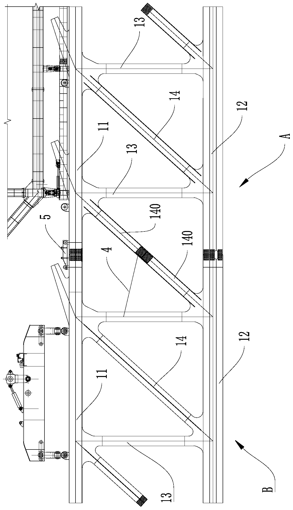
[0052] see Figure 1~3 As shown, the embodiment of the present invention provides a butt joint device for large-segment steel truss girders, which is used for butt jointing two large-segment steel truss girders, and defines two large-segment steel truss girders as erected beam segment A And the beam section B to be erected; the large section steel truss beam includes:

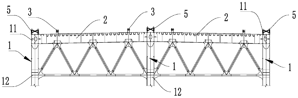
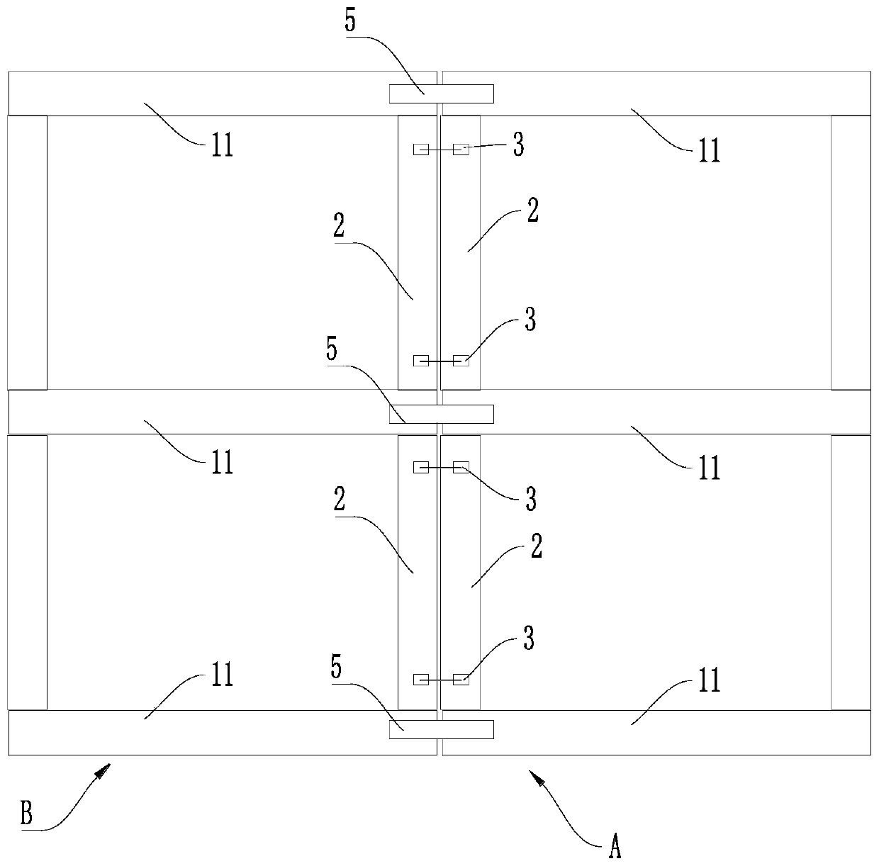
[0053] Several groups of string beam units 1 arranged at intervals in parallel, each string string unit 1 includes an upper string 11, a lower string 12, at least one vertical rod 13 connected to the upper string 11 and the lower string 12, and two The docking rod 140 outside the vertical rod 13;

[0054]A plurality of large crossbeams 2, at least two large crossbeams 2 are arranged between every two adjacent upper chords 11, and two described large crossbeams 2 are respectively arranged at two ends of the two described upper chords 11, to be erected The large beam 2 in the beam section B is set opposite to t...


PUM


Abstract

The invention discloses a connection device for large-section steel truss girders to connect a mounted girder section and a to-be-mounted girder section. The large-section steel truss girder includesan upper chord, a lower chord, a vertical bar, a connection bar, and a large cross girder. The connection device includes a first pulling mechanism, one end of which is connected to a large cross girder of the to-be-mounted girder section, and the other end of which is connected to the corresponding large cross girder in the mounted girder section, wherein when the first pulling mechanism pulls the mounted girder section and the to-be-mounted girder toward each other, the large cross girder in the to-be-mounted girder section approaches the corresponding large cross girder in the mounted girder section; a second pulling mechanisms the two ends of which are located in the middles of the mounted girder section and the to-be-mounted girder section respectively, wherein when the second pullingmechanism pulls the mounted girder section and the to-be-mounted girder toward each other, a connection bar in the to-be-mounted girder section approaches the corresponding connection bar in the mounted girder section; and a jacking mechanism including a jack disposed on the upper chord in the to-be-mounted girder section and having a fixed top, wherein when the jack is raised upward, the to-be-mounted girder section is pressed down. The connection device effectively adjusts the relative deformation between the mounted girder section and the to-be-mounted girder section, and realizes the connection of large-section steel truss girders.

Description

technical field [0001] The invention relates to the technical field of butt jointing of steel truss girders, in particular to a butt joint device and method for large-segment steel truss girders. Background technique [0002] With the rapid development of economy and technological innovation, the span of bridges in transportation construction is gradually becoming longer. Most long-span bridges are cable-stayed bridges, and for cable-stayed bridges, especially heavy-duty cable-stayed bridges for road and rail, compared with solid web beams, steel truss girders can reduce their own weight and increase rigidity. Better suited for load-bearing structures with larger spans. [0003] The installation of steel truss girders is mostly realized through the butt joint of multiple segmental steel truss girders. In the prior art, a conventional butt joint method is to set up a temporary platform under the docking area, and set the steel truss to be erected on the temporary platform. ...

Claims


Application Information

Patent Timeline
IPC IPC(8): E01D21/00
CPCE01D21/00
Inventor 邹冠胡杰张文斌许佳平毛玮琦涂满明李军堂姚森胡勇崔一兵陈涛朱云萍耿豪姜江华贾维君
Owner CHINA RAILWAY MAJOR BRIDGE ENG GRP CO LTD
Why Eureka
Try Eureka