A dry splicing structure of floor tiles and its splicing method

A floor tile, dry-type technology, applied in the direction of building structure, building, floor, etc., can solve the problems of complex floor tile laying technology, environmental impact of construction conditions, and difficulty in guaranteeing construction quality, and achieves good splicing quality and construction efficiency. High, easy splicing effect

Active Publication Date: 2020-06-16
DECAI DECORATION +1
View PDF4 Cites 0 Cited by
  • Summary
  • Abstract
  • Description
  • Claims
  • Application Information

AI Technical Summary

Problems solved by technology

[0004] The invention proposes a dry splicing structure of floor tiles and a splicing method thereof, which solves the problems in the prior art of floor tile laying technology such as complex process, long construction period, construction conditions affected by the environment, and difficult construction quality assurance

Method used


Image

  • A dry splicing structure of floor tiles and its splicing method
  • A dry splicing structure of floor tiles and its splicing method
  • A dry splicing structure of floor tiles and its splicing method

Examples


Embodiment 1

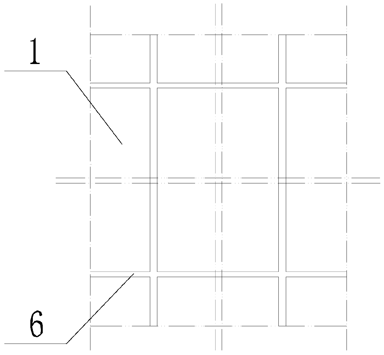
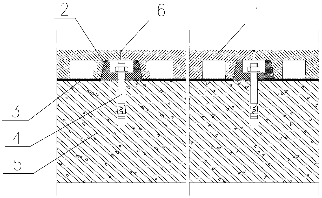
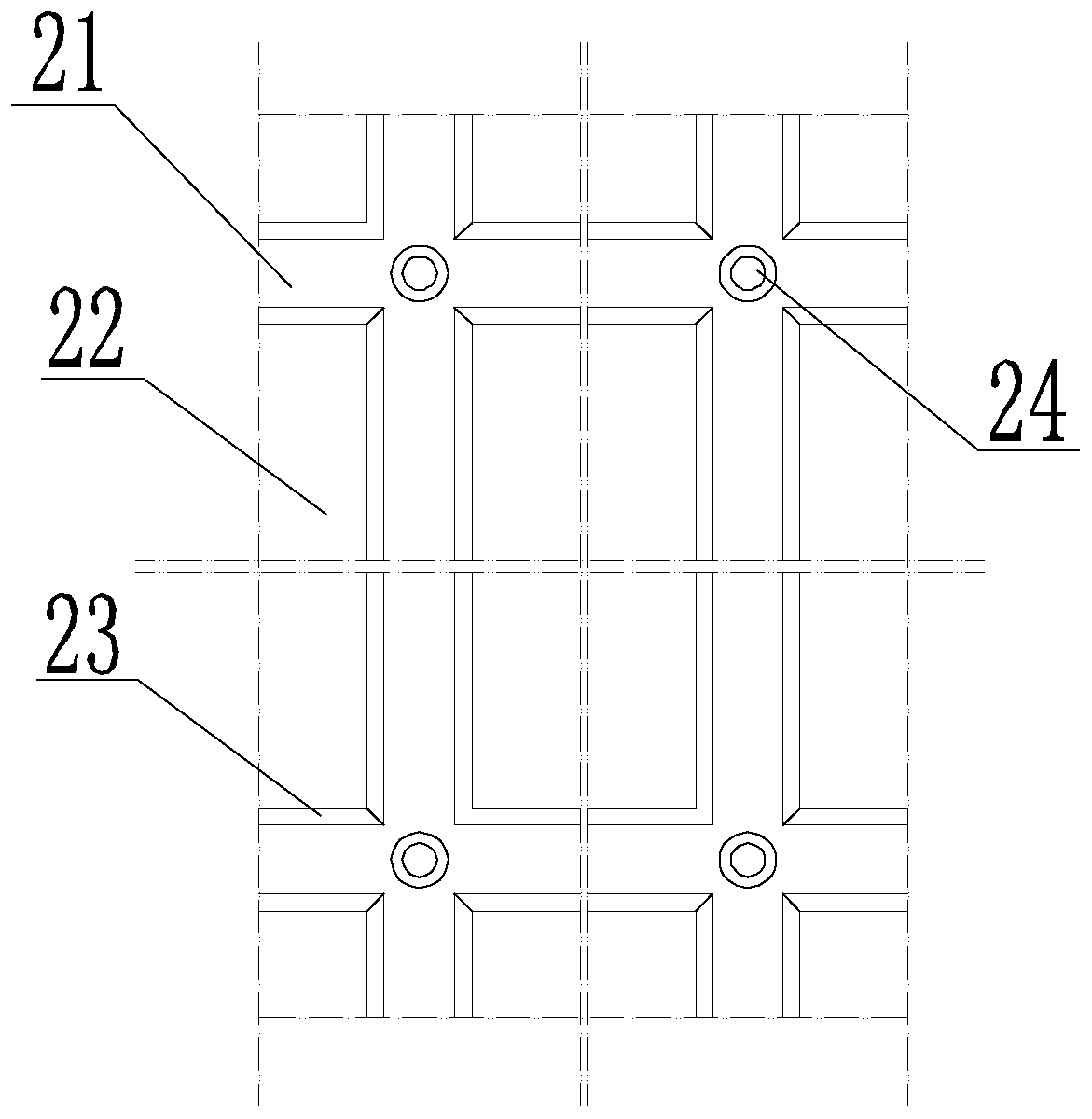
[0026] See attached figure 1 , attached figure 2 , attached image 3 And attached Figure 4 , a dry splicing structure of a floor tile 1 according to the present invention, comprising a paving surface 5, a support frame 2 is provided on the paving surface 5, floor tiles 1 are laid on the support frame 2, and caulking strips 6 are provided between adjacent floor tiles 1 The support frame 2 includes a mounting surface 21 and a mounting groove 22, the support frame 2 is provided with a plurality of mounting grooves 22, the support frame 2 is provided with a mounting surface 21 on the circumference of the mounting groove 22, and the mounting surface 21 is provided with a card groove 23 The floor tile 1 includes a connecting plate 11 and a protrusion 13. The back of the floor tile 1 is provided with a protrusion 13 snapped into the installation groove 22. The connecting plate 11 is located in the circumferential direction of the floor tile 1 and abuts against the installation su...

Embodiment 2

[0033] A splicing method of a floor tile 1 dry type splicing structure of the present invention comprises the following steps: 1) selecting a paving surface 5, and connecting the support frame 2 on the paving surface 5 by the above method; 2) splicing the floor tile 1 on the support frame 2. In this embodiment, the laying surface 5, the support frame 2 and the floor tile 1 all have the structure described in the first embodiment, the laying surface 5 is connected to the support frame 2 through the expansion bolt 4, and the support frame 2 is connected to the support frame 2 through the installation groove 22 and the protrusion 13 As well as the cooperating splicing of the card slot 23 and the card block 12 to connect the floor tile 1, the present invention is a dry splicing method in the true sense. The construction process is simple, the construction efficiency is high, and it is not limited by the ambient temperature. The gap between them is even, the surface is flat, the hei...


PUM


Abstract

The invention provides a floor tile dry-type splicing structure and a splicing method thereof; the structure comprises a pavement surface that has a support; the floor tiles are paved on the support;a caulking strip is arranged between adjacent floor tiles; the support comprises a mounting surface and mounting grooves; the plurality of mounting grooves are arranged on the support; the support sets the mounting surface on the periphery of the mounting grooves; the mounting surface has card slots; the floor tile comprises a connecting plate and bumps; the backside of the floor tile is providedwith the bump that is clamped in the mounting groove; the connecting plate is arranged on the periphery of the floor tile and abuts against the mounting surface; the backside of the connecting plate is provided with a block that is matched with the card slot. The invention also provides the splicing method of the floor tiles; the floor tiles are directly spliced on the support via a dry method without using a cement slurry and a bonding agent; the construction process is simple, has no requirement on construction conditions, is easy in splicing, firm in structure, high in construction efficiency, cannot have bulking, cracking and warpping phenomenon, and the spliced surface is flat and consistent in height.

Description

technical field [0001] The invention relates to the technical field of architectural decoration engineering, in particular to a dry splicing structure of floor tiles and a splicing method thereof. Background technique [0002] Floor tile is a kind of ground decoration material, which is mostly used for the ground and floor of public buildings and civil buildings. The existing floor tile laying technology is usually to first use cement mortar to lay the floor tiles on the ground. During the laying process, it is necessary to use a rubber hammer to strike to ensure the adhesion of the floor tile mortar and avoid hollowing in the later stage; After the mortar is solidified, the joints of the floor tiles are jointed with a powdered jointing agent. [0003] In the above-mentioned floor tile paving technology, due to the use of cement mortar or adhesives for paving, the construction process requirements are relatively high, such as: the mix ratio of cement mortar, water immersion...

Claims


Application Information

Patent Timeline
Patent Type & Authority Patents(China)
IPC IPC(8): E04F15/02E04F15/18
CPCE04F15/02044E04F15/181
Inventor 范旭叶德才杨琦显叶得森刘刚郑巧王龙万莉董飞飞
Owner DECAI DECORATION
Why Eureka
Try Eureka