Compressor rotor and compressor containing same

A compressor rotor and rotor core technology, which is applied in the field of compressors, can solve problems such as insignificant flow effects, reduced compressor efficiency, and limited area, and achieve the effects of improving oil return effects, increasing flow rates, and accelerating speed

Pending Publication Date: 2018-12-18
ZHUHAI GREE REFRIGERATION TECH CENT OF ENERGY SAVING & ENVIRONMENTAL PROTECTION
View PDF4 Cites 0 Cited by
  • Summary
  • Abstract
  • Description
  • Claims
  • Application Information

AI Technical Summary

Problems solved by technology

However, because the area of ​​the rotor that can be used to open flow holes is limited

Method used


Image

  • Compressor rotor and compressor containing same
  • Compressor rotor and compressor containing same
  • Compressor rotor and compressor containing same

Examples


Embodiment 1

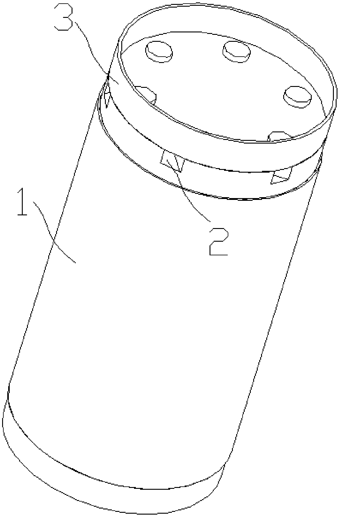
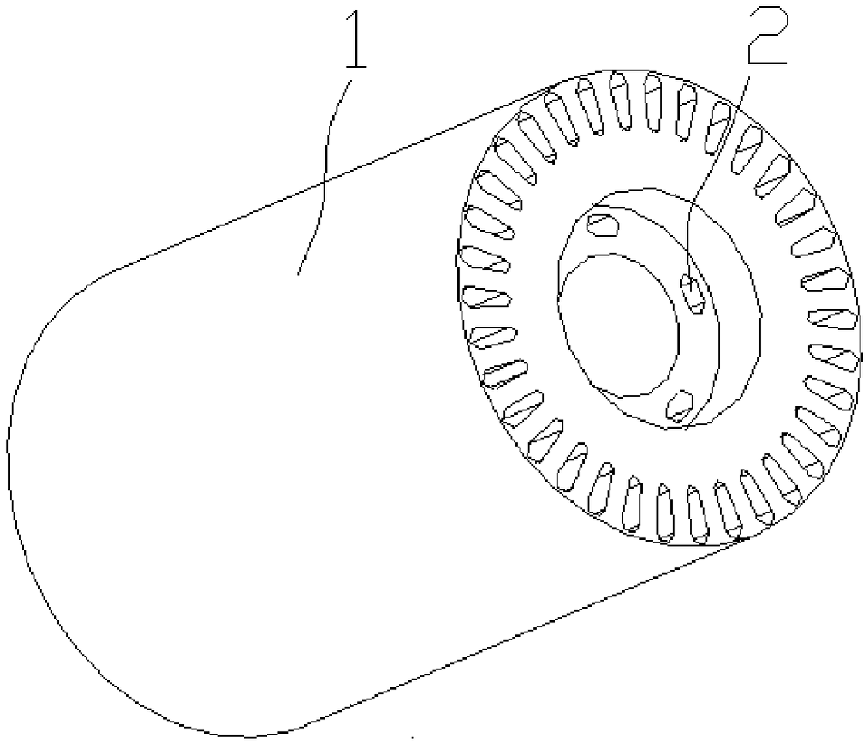
[0036] Please refer to figure 1 , combined with figure 2 -4, this embodiment provides a compressor rotor, including a rotor iron core 1, the rotor iron core 1 is provided with a circulation hole 2 for the circulation of refrigerant, and one end of the rotor iron core 1 is connected with a lower end ring; The other end is connected with a guide structure 3 for guiding the refrigerant to be discharged from the radial direction of the rotor core;

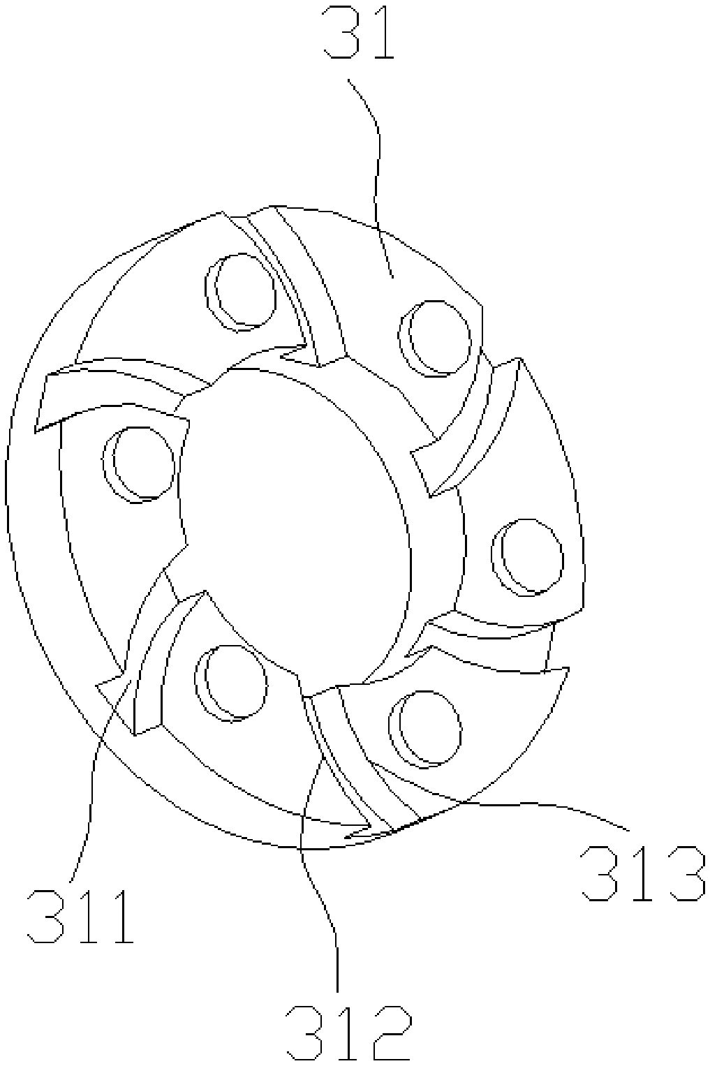
[0037] The diversion structure 3 is provided with one or more flow channels connected with the circulation holes 2 toward the outer peripheral side of the rotor core 1, and the flow channels are used for the circulation of refrigerant; the side of the diversion structure 3 connected with the rotor core 1 is provided with an end The end hole does not penetrate the flow guide structure 3, the end hole covers the flow hole 2 and the axial hole of the rotor, and the flow channel communicates with the end hole.

[0038] The diversion str...


PUM


Abstract

The present invention relates to the technical field of compressors, and in particular relates to a compressor rotor and a compressor including the same. The compressor rotor includes a rotor core, and the rotor core is provided with circulation holes for circulating refrigerants. One end of the rotor core is provided with a lower end ring, and the other end of the rotor core is connected with a flow guiding structure for guiding the refrigerants to be discharged from the radial direction of a rotor, and the flow guiding structure can speed up the flow of the refrigerants flowing through the rotor, and increase the circulation volume of the refrigerants.

Description

technical field [0001] The present invention relates to the technical field of compressors, and in particular, to a compressor rotor and a compressor including the same. Background technique [0002] The motor currently used in the fixed frequency compressor is an induction motor, and its rotor is usually made of cast aluminum. The cast aluminum part forms a closed cage conductor, which generates an induced current in the alternating magnetic field to form a rotor magnetic field, which interacts with the stator magnetic field to drive The motor is running. The conductor aluminum cage can be regarded as three parts, the upper end ring, the aluminum strip, and the lower end ring, which are integrally die-cast during production. [0003] The high-pressure refrigerant compressed by the compressor pump body is discharged upward to the compressor through the stator trimming, the air gap between the stator and the rotor, or the rotor through-hole, etc. The current cast aluminum r...

Claims


Application Information

Patent Timeline
IPC IPC(8): F04B39/06F04B35/04
CPCF04B35/04F04B39/06
Inventor 刘才陈华杰刘锋朱晓光
Owner ZHUHAI GREE REFRIGERATION TECH CENT OF ENERGY SAVING & ENVIRONMENTAL PROTECTION
Why Eureka
Try Eureka