Turnbuckle structure of unmanned aerial vehicle rotor wing

A turnbuckle and machine rotor technology, applied in the field of turnbuckle structure, can solve problems such as complex operation, inability to reduce friction between rotor and nut, and inability to maintain linear balance

Inactive Publication Date: 2018-12-18
江阴航源航空科技有限公司
View PDF7 Cites 0 Cited by
  • Summary
  • Abstract
  • Description
  • Claims
  • Application Information

AI Technical Summary

Problems solved by technology

[0002] In contemporary society, drones are used more and more widely, and more and more people use them. Among them, the rotor has the greatest influence on the flight of drones, and there are many structures in the installation of the rotor. However, the existing turnbuckles have a simple structure and are not easy to operate. The turnbuckles of the multi-rotor drones cannot be t

Method used

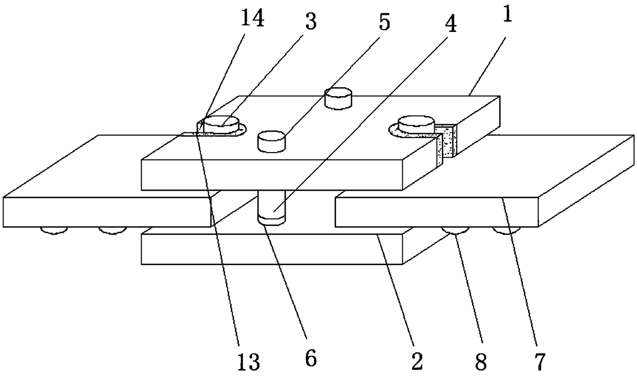

Image

  • Turnbuckle structure of unmanned aerial vehicle rotor wing
  • Turnbuckle structure of unmanned aerial vehicle rotor wing
  • Turnbuckle structure of unmanned aerial vehicle rotor wing

Examples


Embodiment Construction

[0023] The following will clearly and completely describe the technical solutions in the embodiments of the present invention with reference to the accompanying drawings in the embodiments of the present invention. Obviously, the described embodiments are only some, not all, embodiments of the present invention. Based on the embodiments of the present invention, all other embodiments obtained by persons of ordinary skill in the art without making creative efforts belong to the protection scope of the present invention.

[0024] In the description of the present invention, it should be noted that the terms "upper", "lower", "inner", "outer", "front end", "rear end", "both ends", "one end", "another end" The orientation or positional relationship indicated by etc. is based on the orientation or positional relationship shown in the drawings, and is only for the convenience of describing the present invention and simplifying the description, rather than indicating or implying that ...


PUM


Abstract

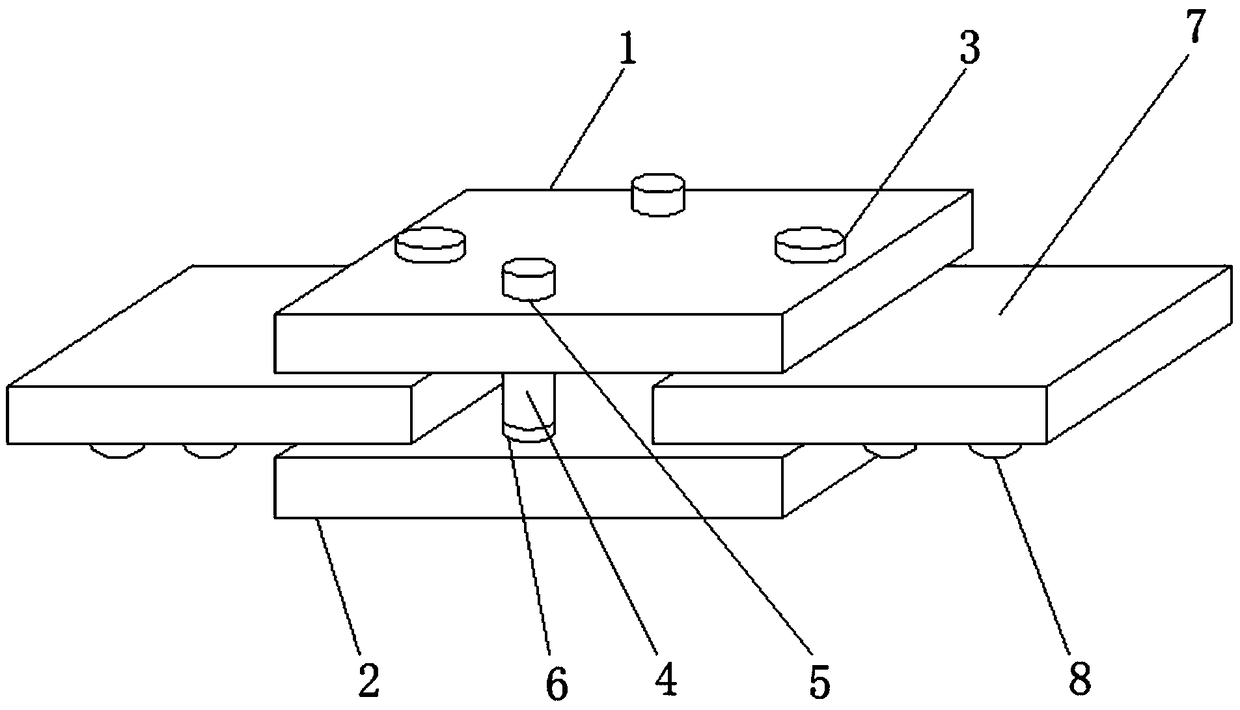
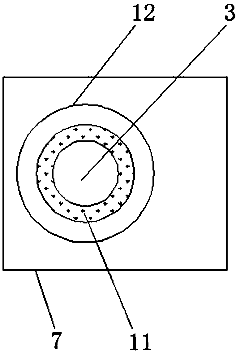
The invention discloses a turnbuckle structure of an unmanned aerial vehicle rotor wing. The turnbuckle structure includes an upper carbon sheet, a lower carbon sheet is movably mounted below the upper carbon sheet, a nut penetrates through the position, close to one side, of the interior of the upper carbon sheet, a groove is formed in the position, close to the nut, of the outer surface of the upper end of the upper carbon sheet, and a screw hole is formed in the outer surface, close to the middle position, of the upper end of the upper carbon sheet; and a screw penetrates through the interior of the screw hole, a screw cap is movably mounted on the outer surface of the upper end of the lower carbon sheet, and the rotor wing is movably mounted between the upper carbon sheet and the lowercarbon sheet. According to the turnbuckle structure, by arranging a series of structures, the turnbuckle structure can be made to convenient to operate in the use process, the ends of the two piecesof rotor wings can have free-rotation gaps so as to maintain the balance of a horizontal line, the beauty of the turnbuckle can be ensured, the operation of a user is facilitated, the friction betweenthe rotor wing and the nut can be reduced, and the service life of the turnbuckle and the rotary wing are prolonged.

Description

technical field [0001] The invention relates to the technical field of turnbuckle structures, in particular to a turnbuckle structure for a drone rotor. Background technique [0002] In contemporary society, drones are used more and more widely, and more and more people use them. Among them, the rotor has the greatest influence on the flight of drones, and there are many structures in the installation of the rotor. However, the existing turnbuckles have a simple structure and are not easy to operate. The turnbuckles of the multi-rotor drones cannot be tightened, otherwise the rotors cannot rotate autonomously and cannot maintain linear balance. The prior art is on the turnbuckles. Glue, but the disadvantage is that it needs to be replaced repeatedly, the operation is complicated and the cost is increased, the friction between the rotor and the nut cannot be reduced, and the service life of the turnbuckle and the rotor is reduced. Contents of the invention [0003] The pur...

Claims


Application Information

Patent Timeline
IPC IPC(8): F16B35/00F16B37/00F16B43/00
CPCF16B35/00F16B37/00F16B43/00B64U30/20
Inventor 马相鸣邹宇涛
Owner 江阴航源航空科技有限公司
Why Eureka
Try Eureka