Ball pouring device for bearing automatic assembly and using method thereof

An automatic assembly and bead filling technology, which is applied to bearing components, shafts and bearings, mechanical equipment, etc., can solve the problems of unfavorable follow-up use, large space occupation, troublesome maintenance, etc., and achieve automation, high working reliability, and replacement The effect of manual manipulation

Pending Publication Date: 2018-12-18
ANHUI UNIVERSITY OF TECHNOLOGY AND SCIENCE +1
View PDF20 Cites 2 Cited by
  • Summary
  • Abstract
  • Description
  • Claims
  • Application Information

AI Technical Summary

Problems solved by technology

[0006] For example, the Chinese Patent Publication No. CN201721793545.8 discloses an automatic assembly device for bearing balls, which includes a base, a first fixing seat arranged at one end of the base, a second fixing seat arranged at the other end of the base, and a second fixing seat arranged on the base and located at The third fixed seat at the position between the first fixed seat and the second fixed seat, the cylinder is fixedly arranged on the first fixed seat, the ball placement groove is fixedly arranged on the third fixed seat, and a ball placement groove is arranged in the ball placement groove A group of balls, the second fixed seat is provided with a rotating shaft, the rotating shaft is equipped with a cage mounting plate, the cylinder is set on the first fixed seat, the cage mounting plate and the ratchet mounting plate are set on the second fixed column, through The cylinder drives the ejector rod and the connecting rod to move. After the ejector rod assembles the balls to the cage, the pawl on the connecting rod drives the ratchet to move, so that the cage mounting plate rotates at a certain angle for the next assembly, which greatly improves the assembly process. The working efficiency is high, but the patent occupies a large space, which is not conducive to transportation and portable use. At the same time, the pawl drives the ratchet to move. There is a possibility that the ratchet will fall off, and maintenance is troublesome, which is not conducive to subsequent use.

Method used


Image

  • Ball pouring device for bearing automatic assembly and using method thereof
  • Ball pouring device for bearing automatic assembly and using method thereof
  • Ball pouring device for bearing automatic assembly and using method thereof

Examples


Embodiment Construction

[0031] In order to make the technical means, creative features, objectives and effects of the present invention easy to understand, the present invention will be further explained below.

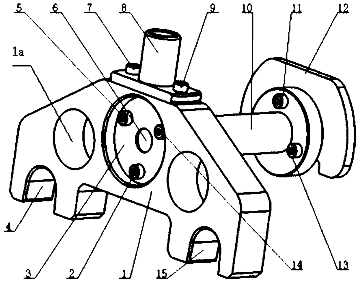
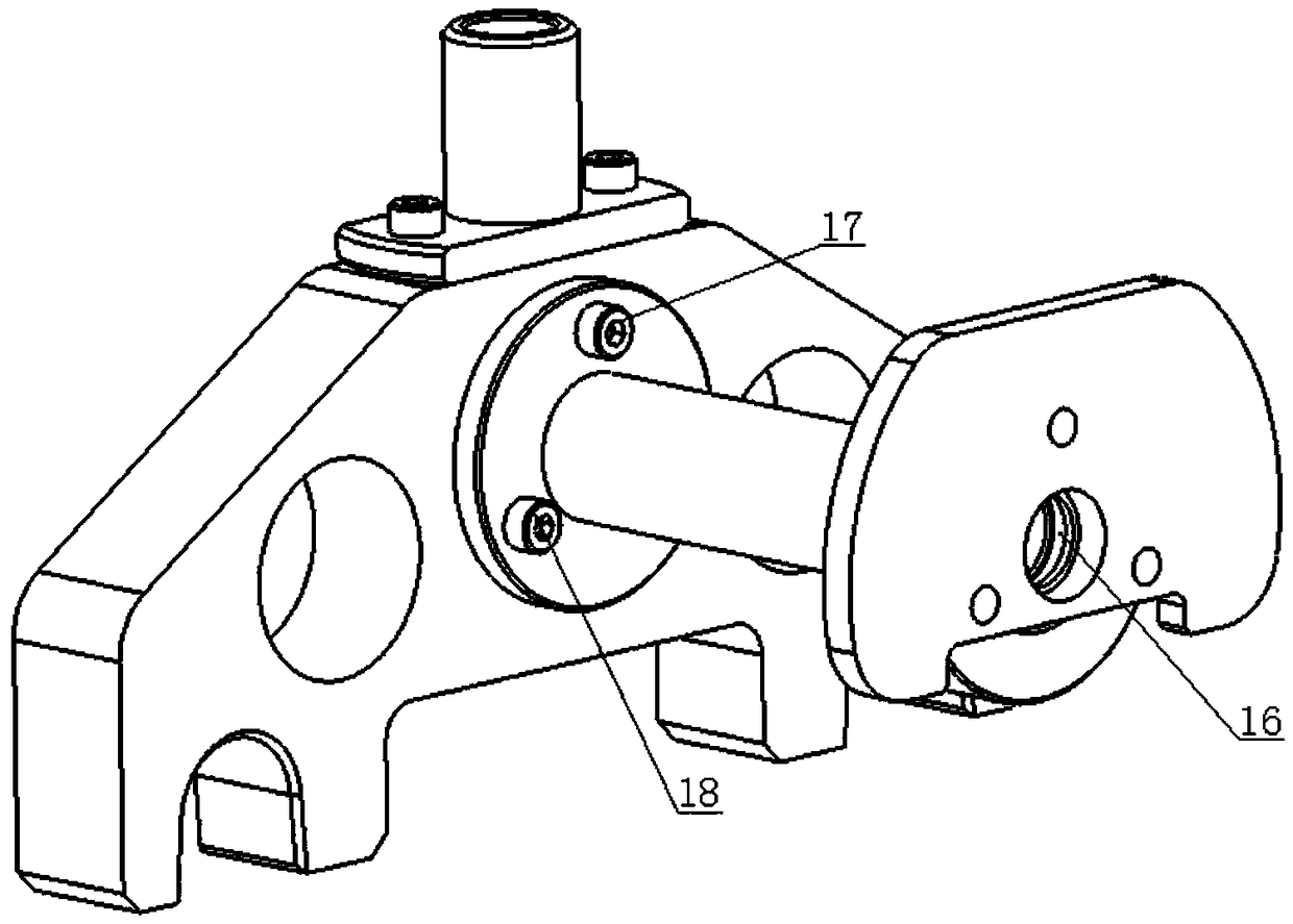
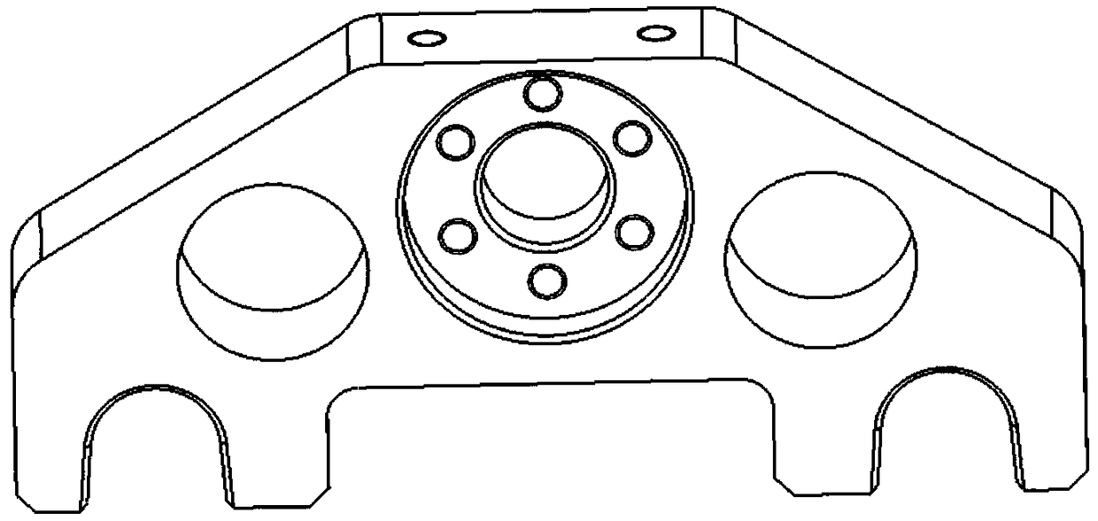
[0032] Such as Figure 1 to Figure 8 As shown, a bead filling device for automatic bearing assembly includes a bead filling holder 1. The upper end of the bead filling holder 1 is provided with a grasping handle 8 that is convenient for robots to grasp. The bead filling holder 1 A ball conveying pipe 10 for conveying balls is provided on one end surface of the ball, and a baffle mechanism that cooperates with the ball conveying pipe 10 is provided on the ball filler bracket 1.

[0033] The grasping handle 8 provided in the present invention is convenient for the robot to grasp.

[0034] The guide groove 1 4 and guide groove 2 15 on the ball filler bracket 1 are configured to facilitate the smooth movement and accurate positioning of the filler on the bearing assembly platform. The ball transfer tu...


PUM


Abstract

The invention relates to a ball pouring device for bearing automatic assembly and a using method thereof. The ball pouring device comprises a ball pouring device support; the upper end of the ball pouring device support is provided with a grabbing handle convenient to grab by a robot; one end face of the ball pouring device support is provided with a ball conveying pipe for conveying balls; and the ball pouring device support is provided with a baffle mechanism matched with the ball conveying pipe. The using method comprises the following specific using steps of (1) grabbing, (2) positioning,and (3) ball pouring. The problem of ball pouring in a narrow roll way of a ball bearing is solved, the working reliability of the whole device is high, automation is conveniently achieved, and manualoperation can be effectively replaced.

Description

Technical field [0001] The invention relates to the application field of robot integration, in particular to a bead filling device for automatic bearing assembly and a use method thereof. Background technique [0002] In order to make the bearing work properly, the correct installation method is very important. After the selection and installation and disassembly methods of the bearing for a specific application are initially determined in the design stage, the installation process needs to be carried out in a clean and dust-free space as much as possible. Subsequent production and assembly are carried out on dusty production machines. Dust and debris will affect internal operations. [0003] Tiny dust can affect the outer diameter of the outer ring, and even cause a gap in the tight fit, which will cause the outer ring of the bearing to run poorly. [0004] In recent years, robots have been widely used in the field of machinery manufacturing, which has continuously improved the deg...

Claims


Application Information

Patent Timeline
Patent Type & Authority Applications(China)
IPC IPC(8): F16C43/06
CPCF16C43/06
Inventor 江本赤杨明苏学满刘玉飞许曙许德章方明王园梁艺
Owner ANHUI UNIVERSITY OF TECHNOLOGY AND SCIENCE
Why Eureka
Try Eureka