
An engineering optical cable conductor with an intermediate joint structure

A technology for intermediate joints and optical cables, applied in the directions of light guide, fiber mechanical structure, optics, etc., can solve the problems of insufficiency and low utilization of wire joints, and achieve the effect of complete structure, not easy to loosen, and ensure structural strength.

Active Publication Date: 2020-02-14
FUZHOU ONE SUN POWER CONSULTING
View PDF5 Cites 0 Cited by
  • Summary
  • Abstract
  • Description
  • Claims
  • Application Information

AI Technical Summary

Problems solved by technology

[0004] The object of the present invention is to provide an engineering optical cable conductor with an intermediate joint structure to solve the problem of the existing engineering optical cable conductors proposed in the above-mentioned background technology. Wire connection, that is, the end-to-end connection between two groups of wires that play the same transmission role, and transmit signals. This transmission and assembly method has great limitations in the multi-directional transmission of signals, and the utilization of wire joints is also low. , unable to meet the requirements of complex or special circumstances, such as the need to save the space occupied by the terminal as much as possible, in this case, the traditional wire connector has obvious disadvantages

Method used


Image

  • An engineering optical cable conductor with an intermediate joint structure
  • An engineering optical cable conductor with an intermediate joint structure
  • An engineering optical cable conductor with an intermediate joint structure

Examples


Embodiment Construction

[0030] The following will clearly and completely describe the technical solutions in the embodiments of the present invention with reference to the accompanying drawings in the embodiments of the present invention. Obviously, the described embodiments are only some of the embodiments of the present invention, not all of them. Based on the embodiments of the present invention, all other embodiments obtained by persons of ordinary skill in the art without making creative efforts belong to the protection scope of the present invention.

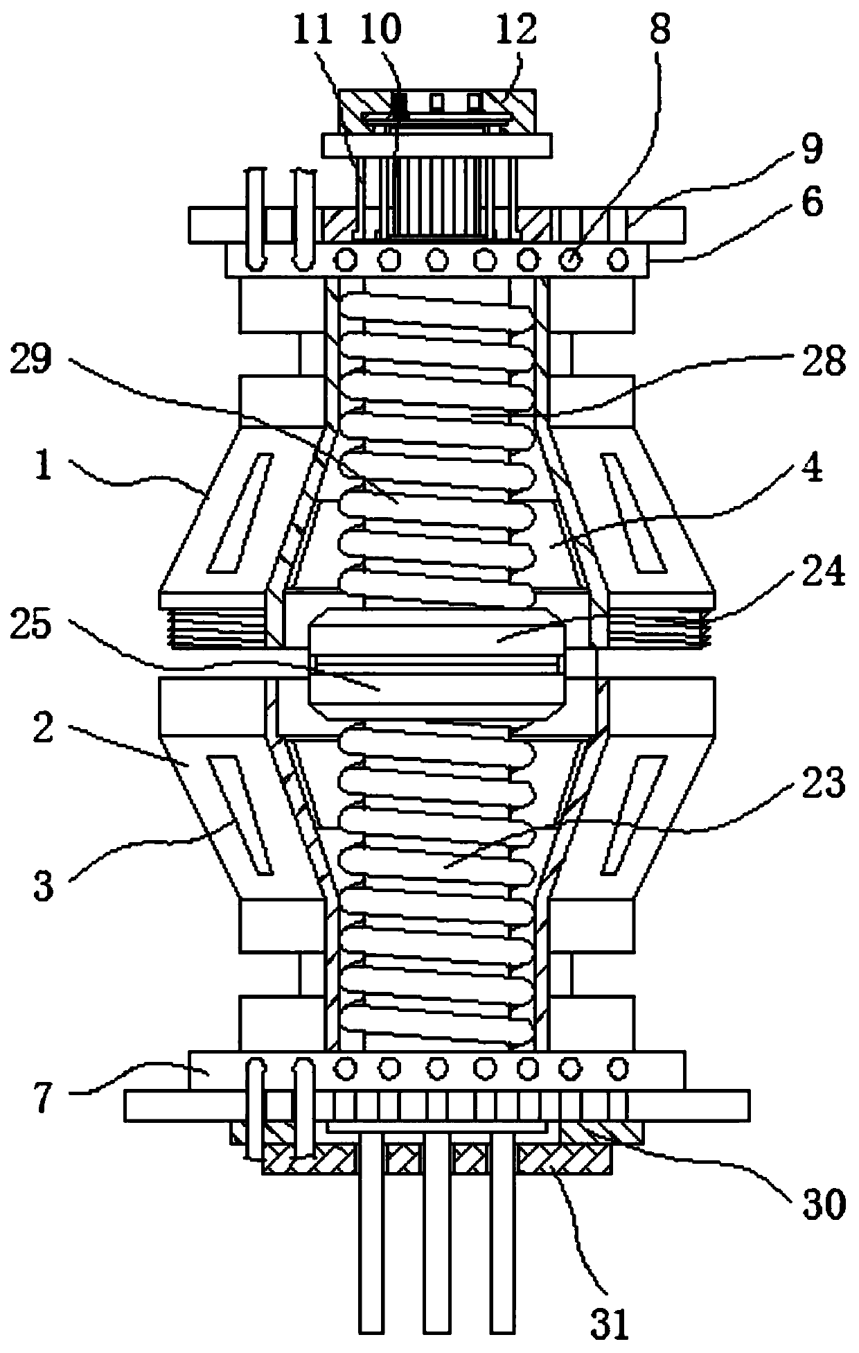
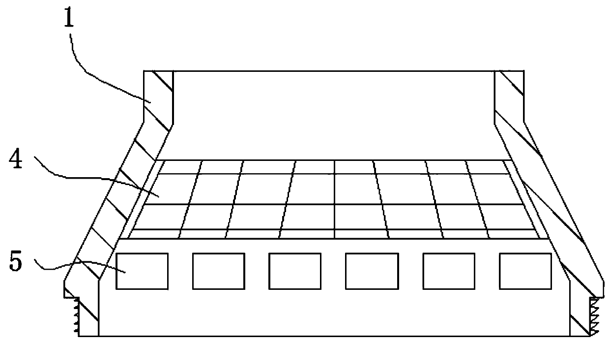
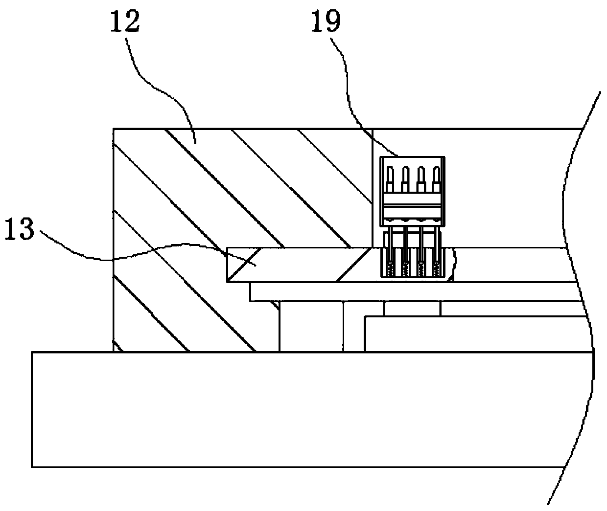
[0031] see Figure 1-8, the present invention provides a technical solution: an engineering optical cable conductor with an intermediate joint structure, including an upper cover 1, an upper connecting end cover 6 and a lower connecting end cover 7, and a lower cover is installed under the upper cover 1 cover 2, and the connection between the lower cover 2 and the upper cover 1 is screw fit, the outer walls of the upper cover 1 and the lower cove...


PUM


Abstract

The invention discloses an engineering optical cable wire with an intermediate joint structure. The engineering optical cable wire comprises an upper cover, an upper drop-out end cover and a lower drop-out end cover; a lower cover is arranged below the upper cover, and the lower cover and the upper cover are in threaded connection; wire through holes are formed on outer walls of the upper drop-outend cover and the lower drop-out end cover, and the upper drop-out end cover and the lower drop-out end cover are respectively located at an upper surface of the upper cover and the lower surface ofthe lower cover; through the threaded connection arrangement between the upper cover and the lower cover of the engineering optical cable wire with the intermediate joint structure, the whole joint structure is complete and convenient for disassembling; a radiating notch is used for radiating, a thermal insulation plate is used for preventing the wire connection section from cold injury caused byover-cold air under the cold environment; a temperature sensor in the same model can be arranged in a temperature sensor opening, thereby monitoring the internal temperature after the upper cover andthe lower cover are connected; the personnel is convenient for adjusting over-high heat or over-low temperature, thereby ensuring the connection quality of the wire connection section.

Description

technical field [0001] The invention relates to the technical field of engineering optical cable conductors, in particular to an engineering optical cable conductor with an intermediate joint structure. Background technique [0002] Optical cables are manufactured to meet optical, mechanical or environmental performance specifications. It is a communication cable assembly that uses one or more optical fibers placed in a sheath as a transmission medium and can be used individually or in groups. Optical cables It is mainly composed of optical fiber (glass filament as thin as hair), plastic protective sleeve and plastic sheath. There is no metal such as gold, silver, copper and aluminum in the optical cable, and generally has no recycling value. Engineering optical cable conductors play a very important role in modern technology. With the advancement of science and technology, the functional transformation and development of engineering optical cable conductors are also activel...

Claims


Application Information

Patent Timeline
Patent Type & Authority Patents(China)
IPC IPC(8): G02B6/44
CPCG02B6/4429G02B6/4439
Inventor 陈振华王福明王圣兵陈杨健李文麟
Owner FUZHOU ONE SUN POWER CONSULTING
Learn More