Liquid crystal display device and application thereof
A liquid crystal display and device technology, applied in the field of liquid crystal display, can solve problems such as limited use, high driving voltage, and application restrictions, and achieve the effect of repeated cycle use, simple driving mode, and reduced driving mode
- Summary
- Abstract
- Description
- Claims
- Application Information
AI Technical Summary
Problems solved by technology
Method used
Image
Examples
Embodiment 1
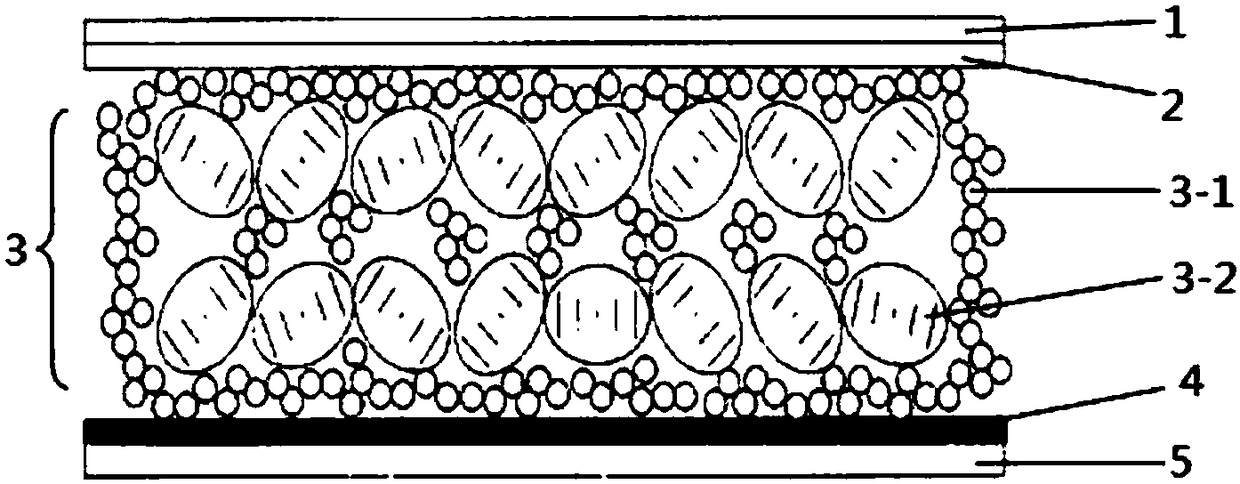
[0045] Add appropriate optically active substances to HPC850100-100 to adjust it to a cholesteric reflection wavelength of about 546nm, pre-dissolve 80mL of dichloromethane 1g PMMA prepolymer and doped with 1wt% polymethacrylic acid (PMAA) After mixing 400mL of the aqueous solution, add 20g of cholesteric liquid crystals, mix uniformly to form an emulsion, remove methylene chloride by solvent evaporation, and obtain an aqueous solution containing liquid crystal microcapsules with a diameter of about 10 μm (which contains about 50wt% liquid crystal microcapsules). Then the prepared liquid crystal microcapsule aqueous solution and 20wt% PVA aqueous solution are mixed evenly at a volume ratio of 1:1, and set aside.
[0046] Select a conductive PET-ITO with a thickness of 125 μm as the first substrate, place it on a film coating machine, and apply a layer of OCA optical adhesive with a thickness of 20 μm on the surface of the substrate using the screw printing technology (purchased...
Embodiment 2
[0049] The preparation method of the aqueous solution of liquid crystal microcapsules in this example is basically the same as in Example 1, except that the liquid crystal in Example 1 is replaced with HSG07900-000, and the cholesteric reflection wavelength is replaced with about 625nm. Then the prepared liquid crystal microcapsule aqueous solution and 20wt% bone glue aqueous solution are mixed evenly in a volume ratio of 4:6, and set aside.
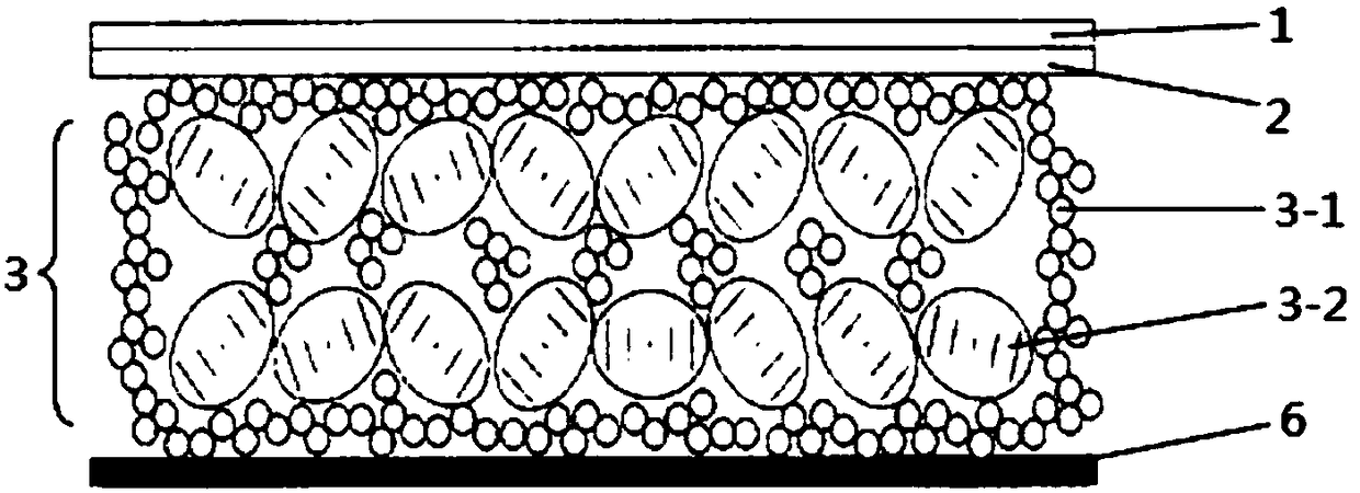
[0050] Select conductive PET-ITO with a thickness of 75 μm as the first substrate, place it flat on the film coating machine, and apply a layer of OCA optical glue with a thickness of 20 μm on the surface of the substrate by screw printing technology. After drying for 3 minutes, polymerize and cure for 3 minutes under 8mW illumination and 365nm fluorescent lamp. Then, the liquid crystal microcapsule solution mixed with bone glue prepared above was coated with a thickness of 40 μm on the surface of the OCA optical glue by scraper printing...
Embodiment 3
[0053] Mix HMT138600-100I001 and 33wt% aqueous polyurethane solution at a volume ratio of 6:4, stir at a stirring rate of 1000rmp for 5 minutes, and defoam to obtain a suspoemulsion. Liquid crystal particles with a particle size of about 15 μm can be seen under a microscope. In water-based polyurethane, spare.
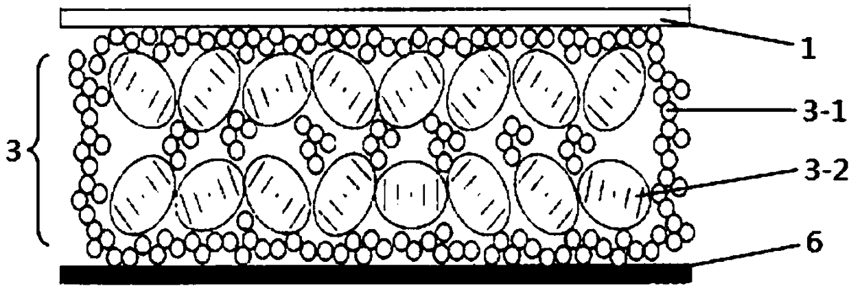
[0054] Select the conductive PET-ITO with a thickness of 188 μm as the first substrate, put it on the film coating machine and place it flat, and use the screw printing technology to coat a layer of the above-mentioned water-based polyurethane mixed with water-based polyurethane with a thickness of 30 μm on the surface of the substrate. Liquid crystal emulsion, dried at 80°C for 5 hours. Then, a layer of black conductive adhesive with a thickness of 20 μm is coated on the film by scraper printing technology, and dried at 50° C. for 0.5 hour to prepare the liquid crystal display device of the present invention.
[0055] The structure of the prepared liquid crystal disp...
PUM
| Property | Measurement | Unit |
|---|---|---|
| thickness | aaaaa | aaaaa |
| diameter | aaaaa | aaaaa |
| wavelength | aaaaa | aaaaa |
Abstract
Description
Claims
Application Information
 - R&D
- Intellectual Property
- Life Sciences
- Materials
- Tech Scout
- Unparalleled Data Quality
- Higher Quality Content
- 60% Fewer Hallucinations
Browse by: Latest US Patents, China's latest patents, Technical Efficacy Thesaurus, Application Domain, Technology Topic, Popular Technical Reports.
© 2025 PatSnap. All rights reserved.Legal|Privacy policy|Modern Slavery Act Transparency Statement|Sitemap|About US| Contact US: help@patsnap.com


