
A wireless charging coil for a multi-rotor unmanned aerial vehicle

A wireless charging and coil technology, applied in circuits, inductors, electrical components, etc., can solve the problems of large coupling coefficient offset distance, small size of multi-rotor drones, and errors in fixed-point landing, and achieve small size. , the effect of enhancing offset tolerance and reducing leakage inductance

Inactive Publication Date: 2018-12-18
TSINGHUA UNIV
View PDF6 Cites 4 Cited by
  • Summary
  • Abstract
  • Description
  • Claims
  • Application Information

AI Technical Summary

Problems solved by technology

However, the current wireless charging system is mostly based on the wireless charging of electric vehicles. The charging coils mostly adopt a symmetrical structure between the receiving end and the transmitting end. Features such as small load and errors in fixed-point landing

Method used


Image

  • A wireless charging coil for a multi-rotor unmanned aerial vehicle
  • A wireless charging coil for a multi-rotor unmanned aerial vehicle
  • A wireless charging coil for a multi-rotor unmanned aerial vehicle

Examples


Embodiment Construction

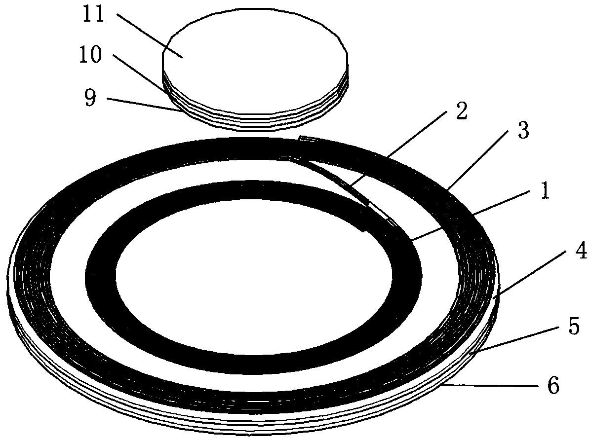
[0018] The wireless charging coil for the multi-rotor UAV proposed by the present invention has a structure such as figure 1 As shown, it includes a transmitting coil and a receiving coil, the transmitting coil and the receiving coil are coupled to each other, and the uppermost transmitting coil layer in the transmitting coil is opposite to the receiving coil layer in the receiving coil.

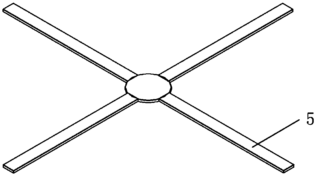
[0019] In the above wireless charging coil, the transmitter coil includes a transmitter coil layer, a transmitter support layer 4, a transmitter magnetic medium layer 5, a transmitter magnetic shielding layer 6 and a transmitter protective shell 7, such as figure 2 shown in . The transmitter coil layer, the transmitter support layer 4 , the transmitter magnetic medium layer 5 and the transmitter magnetic shielding layer 6 are laminated and tightly fixed from top to bottom and placed in the transmitter protective shell 7 . The coil layer at the transmitting end is composed of an inner helic...


PUM

PropertyMeasurementUnit
Thicknessaaaaaaaaaa

Abstract

The invention relates to a wireless charging coil for a multi-rotor unmanned aerial vehicle, belonging to the technical field of multi-rotor unmanned aerial vehicle autonomous charging. The wireless charging coil comprises a transmitting end coil and a receiving end coil, wherein the transmitting end coil and the receiving end coil are coupled with each other, and an uppermost coil layer in the transmitting end coil is opposite to a receiving end coil layer in the receiving end coil. The wireless charging coil of the invention has small outer diameter of the receiving end coil and no magneticdielectric layer at the receiving end, effectively reducing the volume and weight of the receiving end, and satisfying the characteristics of small volume and small load of a multi-rotor unmanned aerial vehicle. Wherein the outer diameter of the transmitting end coil is larger than that of the receiving end coil, two concentric coil groups with different radii are connected in series, The magneticflux density generated by the transmitting end plane is relatively uniform on the charging platform, and the charging characteristics of the system remain stable even when the receiving end deviatesgreatly, which enhances the tolerance of the transmitting end to the receiving end deviation and satisfies the characteristics of the fixed-point landing error of the multi-rotor unmanned aerial vehicle.

Description

technical field [0001] The invention relates to a wireless charging coil for a multi-rotor UAV, and belongs to the technical field of multi-rotor UAV autonomous charging. technical background [0002] Due to its simple structure, flexible maneuverability, strong adaptability, zero casualties and many other advantages, UAVs have broad application prospects in scientific research, civil and military fields. At present, there are more than 30 countries engaged in the research and production of UAVs in the world, and the number of basic types of UAVs has increased to more than 300. Its control algorithm is becoming more and more mature, but endurance is still an obstacle to the further development of UAVs. important question. Most of the drones are powered by lithium batteries, and the endurance is limited by the battery capacity, generally only about 30 minutes. The degree of intelligence of the drone also seriously restricts the execution of mid-range and long-distance tasks...

Claims


Application Information

Patent Timeline
IPC IPC(8): H01F38/14
CPCH01F38/14
Inventor 孙新亚宋义岐董炜吉吟东
Owner TSINGHUA UNIV
Learn More