A method for control peak load regulation of ultra-high voltage receiving terminal power network

A receiving-end power grid and control method technology, applied in the direction of AC network voltage adjustment, single-network parallel feed arrangement, AC network load balancing, etc., can solve problems such as difficulty in peak regulation and power balance of UHV receiving-end power grid

Inactive Publication Date: 2018-12-18
STATE GRID HEBEI ELECTRIC POWER RES INST +2
View PDF4 Cites 8 Cited by
  • Summary
  • Abstract
  • Description
  • Claims
  • Application Information

AI Technical Summary

Problems solved by technology

[0004] In view of this, the embodiment of the present invention provides a method for peak regulation control of the UHV receiving-en

Method used


Image

  • A method for control peak load regulation of ultra-high voltage receiving terminal power network
  • A method for control peak load regulation of ultra-high voltage receiving terminal power network
  • A method for control peak load regulation of ultra-high voltage receiving terminal power network

Examples


Embodiment 2

[0104] like Image 6 As shown, in one embodiment of the present invention, Image 6 A UHV receiving end power grid peak regulation control device 100 shown is used to implement figure 1 The method step in the corresponding embodiment, it comprises:

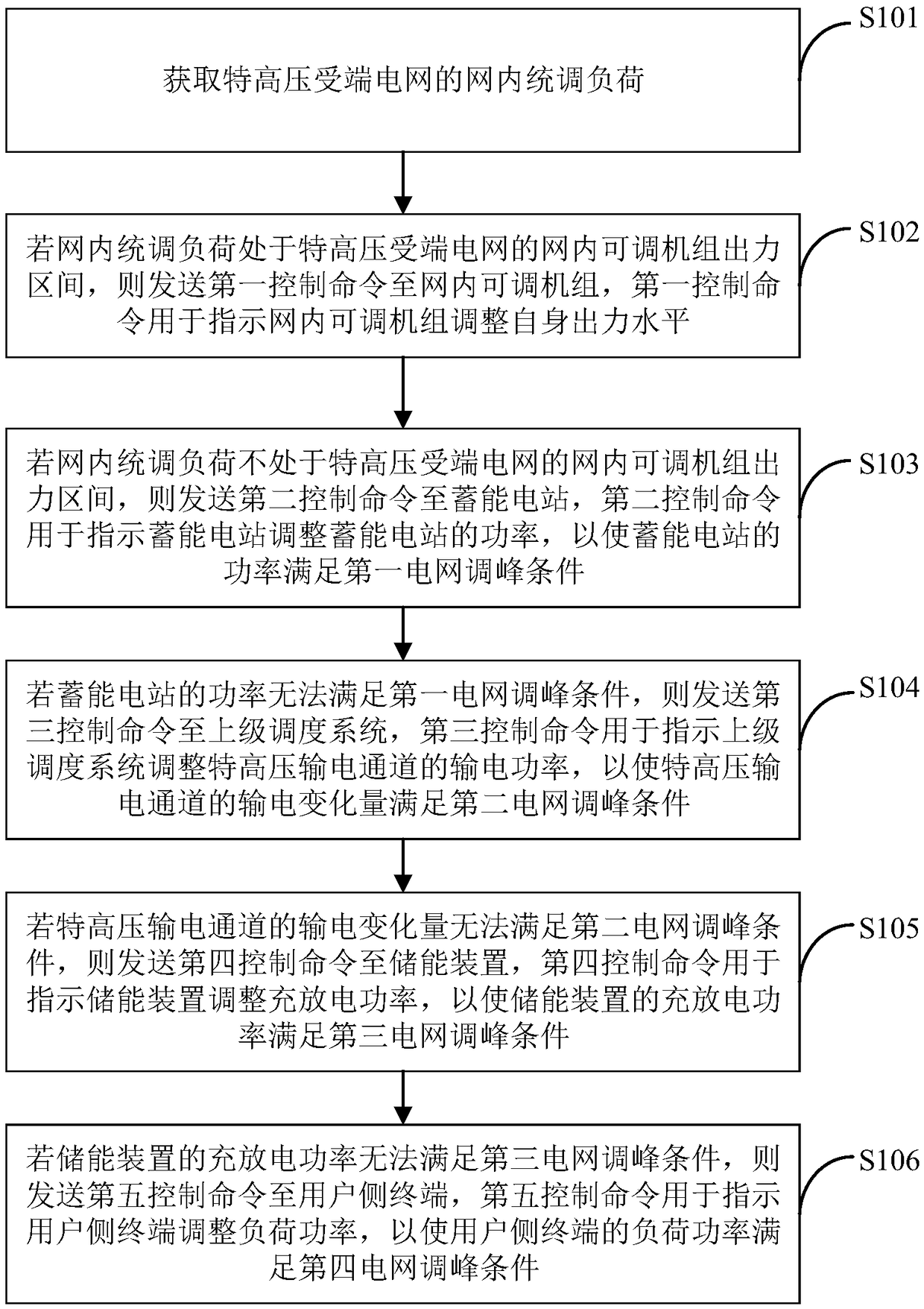
[0105] The in-network unified load acquisition module 110 is used to acquire the in-network unified load of the UHV receiving end power grid;

[0106] The first control command sending module 120 is used to send the first control command to the adjustable unit in the network if the unified regulation load in the grid is in the output range of the adjustable unit in the UHV receiving end grid. The first control command is used for Instruct the adjustable unit in the network to adjust its own output level;

[0107] The second control command sending module 130 is used to send the second control command to the energy storage power station if the in-grid regulated load is not in the output range of the in-grid adjustable unit of th...

Embodiment 3

[0143] Figure 7 It is a schematic diagram of a terminal device provided by an embodiment of the present invention. like Figure 7 As shown, the terminal device 7 of this embodiment includes: a processor 70 , a memory 71 and a computer program 72 stored in the memory 71 and operable on the processor 70 . When the processor 70 executes the computer program 72, it realizes the steps in the above-mentioned embodiments of the peak-shaving control method of the UHV receiving end power grid, for example figure 1 Steps 101 to 106 are shown. Alternatively, when the processor 70 executes the computer program 72, it realizes the functions of the modules / units in the above-mentioned device embodiments, for example Image 6 The functions of the modules 110 to 160 are shown.

[0144] Exemplarily, the computer program 72 can be divided into one or more modules / units, and the one or more modules / units are stored in the memory 71 and executed by the processor 70 to complete this inventio...


PUM


Abstract

The invention is applicable to the technical field of power network dispatching, and provides an UHV receiving-end power network peak load regulation control method, comprising the following steps: obtaining the UHV receiving-end power network in-network unified load regulation; If the load in the network is in the output range of the adjustable unit, the output level of the adjustable unit in thenetwork will be adjusted. If the load in the network is not in the output range of the adjustable unit, the power of the storage power station will be regulated. If the power of the storage power station can not meet the peak load regulation condition of the first power network, the transmission power of the UHV transmission channel is regulated. If the transmission variation of the UHV transmission channel can not meet the peak load regulation condition of the second power network, the charging and discharging power of the energy storage device is regulated. If the charging and discharging power of the energy storage device cannot meet the peak load regulation condition of the third power network, the load power of the terminal on the user side is adjusted so that the load power of the terminal on the user side meets the peak load regulation condition of the fourth power network. The invention can realize the peak clipping and valley filling of the power network, and ensure the safeand stable operation of the power network and the reliable power supply.

Description

technical field [0001] The invention belongs to the technical field of power grid dispatching, and in particular relates to a peak-shaving control method for an UHV receiving-end power grid. Background technique [0002] With the rapid development of UHV power grid and new energy power generation, the UHV receiving end power grid is facing the dual pressure of simultaneously consuming distant clean power and fully consuming local new energy power. In the northern region, winter is faced with the multiple constraints of a high proportion of thermal power heating units, limited peak shaving depth, and serious shortage of peak shaving power sources such as hydropower and natural gas power generation. In addition, under the situation of air pollution prevention and control, the use of heat to determine power is even more serious. Limit the means of power grid peak regulation. Especially during the winter holidays, the industrial production load is significantly reduced, the bas...

Claims


Application Information

Patent Timeline
IPC IPC(8): H02J3/28H02J3/46H02J3/14
CPCH02J3/14H02J3/28H02J3/46
Inventor 梁纪峰胡文平丁斌胡雪凯饶群李晓军
Owner STATE GRID HEBEI ELECTRIC POWER RES INST
Why Eureka
Try Eureka