Injection device for automatic salted fish processing device

A technology of automatic processing and injection device, applied in the field of food processing, can solve problems such as destroying the integrity of fish meat, and achieve the effects of avoiding damage, saving time and improving work efficiency

Inactive Publication Date: 2018-12-21
郑立辉
View PDF5 Cites 5 Cited by
  • Summary
  • Abstract
  • Description
  • Claims
  • Application Information

AI Technical Summary

Problems solved by technology

[0005] The practical invention overcomes the above-mentioned deficiencies in the prior art, and provides an injection device for an automatic processing device for salted fish, which is used to

Method used


Image

  • Injection device for automatic salted fish processing device
  • Injection device for automatic salted fish processing device
  • Injection device for automatic salted fish processing device

Examples


specific Embodiment approach 1

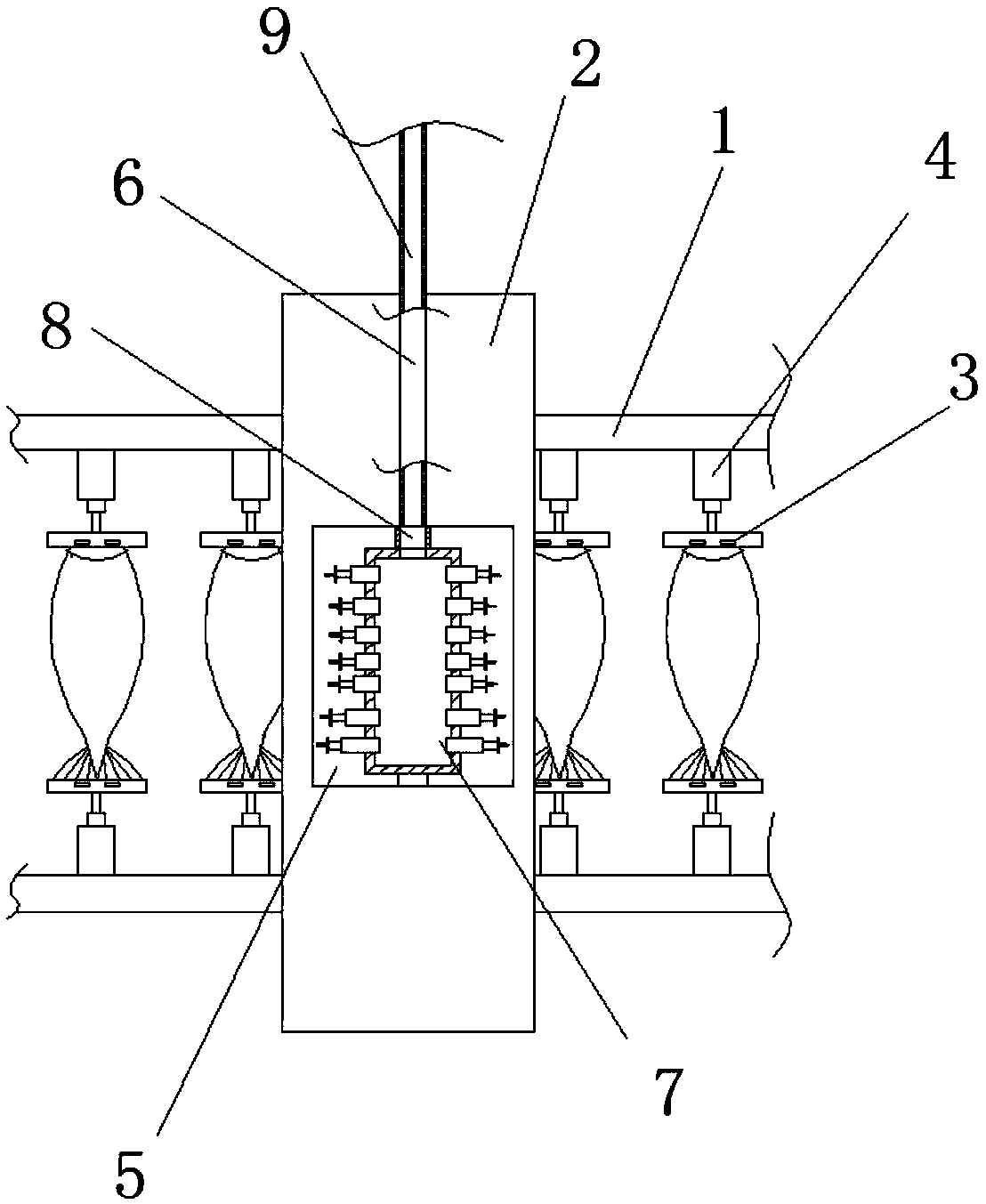
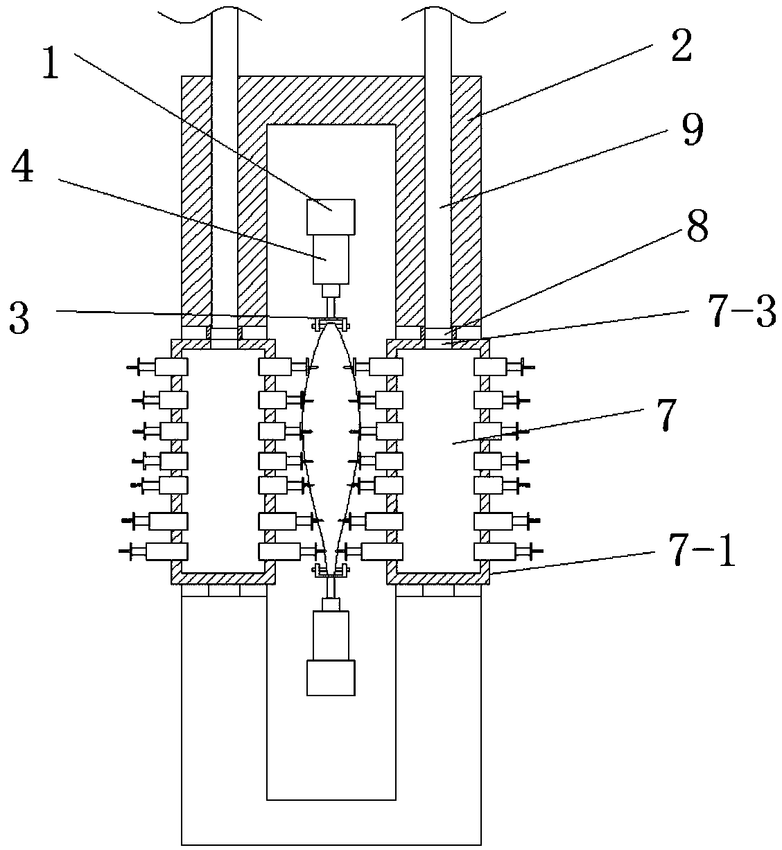
[0027] Such as Figure 1 to Figure 5 As shown, a salted fish automatic processing device disclosed in this embodiment includes a transmission device 1, a fixed frame 2, a fixed clip 3, a cylinder 4, an injection device 7, a hollow rotating shaft 8 and an infusion tube 9; two transmission devices 1 are parallel Set in the fixed frame 2, multiple sets of fixed clips 3 are symmetrically arranged on two parallel transmission devices 1 through the cylinder 4, the two side walls of the fixed frame 2 are symmetrically opened with a rectangular groove 5, and the upper end of the rectangular groove 5 is opened with a through cavity 6, The upper and lower ends of the injection device 7 are respectively arranged in the rectangular groove 5 through the hollow rotating shaft 8 and the rotating shaft. One end of the infusion tube 9 is connected with the high-pressure water pump, and the other end is arranged in the hollow rotating shaft 8 through the cavity 6;

[0028] Such as figure 1 wit...

specific Embodiment approach 2

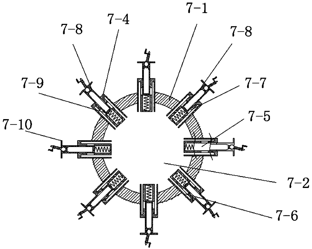
[0034] combine Image 6 with 7 As shown, this embodiment is based on the first embodiment, the difference is that the elastic member 7-8-10 includes a connecting piece 7-8-11, a pressing rod 7-8-12, and a pressing roller 7-8 -13, the second pressure spring 7-8-14, the fixed rod 7-8-15 and the limit protrusion 7-8-16; one end of the connecting piece 7-8-11 and the limit ring 7-8-8 The side walls are connected, and one end of the symmetrically arranged pressure rod 7-8-12 is connected through the pressure roller 7-8-13, and the other end passes through the second pressure spring 7-8-14 and the connecting piece 7-8-11 in sequence, And be connected by fixed rod 7-8-15, one end of the second pressure spring 7-8-14 links to each other with connecting piece 7-8-11, and the other end is connected with the limit protrusion on the side wall of pressure rod 7-8-12 From 7-8-16 connected;

[0035] The changing process of the power of elastic member 7-8-10, the pushing force of beginning...

specific Embodiment approach 3

[0036] combine Figure 4 with 5 , this embodiment is based on the first embodiment, the difference is that the elastic member 7-8-10 includes a connecting piece 7-8-11, a pressing rod 7-8-12, and a pressing roller 7-8-13 , the second pressure spring 7-8-14, the fixed rod 7-8-15 and the limit protrusion 7-8-16; one end of the connecting piece 7-8-11 and the side wall of the limit ring 7-8-8 Connected, one end of the symmetrically arranged pressure rod 7-8-12 is connected through the pressure roller 7-8-13, and the other end passes through the second pressure spring 7-8-14 and the connecting piece 7-8-11 in turn, and passes through The fixed rod 7-8-15 is connected, and one end of the second pressure spring 7-8-14 is connected with the connecting piece 7-8-11, and the other end is connected with the limit protrusion 7 on the side wall of the pressure rod 7-8-12 -8-16 connected.

[0037] Further, the distance from the highest point of the pressure roller 7-8-13 to the connecti...


PUM


Abstract

The invention relates to the technical field of food processing, and specifically relates to an injection device for an automatic salted fish processing device. The injection device comprises an injection roller, first cylinder bodies, an injector, a first pressing spring and a limiting sheet, wherein a columnar chamber is formed in the injection roller, and an infusion hole is formed in the top wall of the columnar chamber; a plurality of first cylinder bodies are symmetrically arranged on the sidewall of the columnar chamber; a groove is formed in the end surface of one end, at the outer part of the columnar chamber, of each first cylinder body; infusion grooves are symmetrically formed in the end surfaces of the ends, in the columnar chamber, of the first cylinder bodies; the grooves are positioned between two infusion grooves and communicate with the two infusion grooves through first liquid inlet holes; the bottom part of the injector is movably arranged in each groove. Accordingto the device, the injection is continuously performed in a rolling manner, so that the problems that the injection is intermittently stopped and the fish is damaged by force between an injection needle and fresh fish can be overcome while the injection uniformity is ensured, and the working efficiency is improved; the injection needle can effectively move in and out of the fish body, and the fishis complete and is not broken.

Description

technical field [0001] The invention belongs to the technical field of food processing, and in particular relates to an injection device for an automatic salted fish processing device. Background technique [0002] Saline injection of meat products is a kind of wet pickling method. The common wet pickling method is to directly marinate the meat products in a prepared salt solution, while the salt water injection method is to inject the pickling solution directly into the meat through a needle. In products, this method can shorten the marinating time and the marinating effect is better. However, the brine injection machine in the existing salted fish automatic processing is that the vertical or horizontal injection needles arranged in one direction cooperate with the intermittently conveyed fish meat on the transmission belt. When the transmission belt drives the fish to the position corresponding to the injection needle, the transmission belt Stop, injection Injection for f...

Claims


Application Information

Patent Timeline
IPC IPC(8): A23L17/00A23P30/00
CPCA23L17/00A23P30/00
Inventor 郑立辉
Owner 郑立辉
Why Eureka
Try Eureka